 As the wireless receiver sensitivity levels surpass thermal noise levels, reliable operation of smart grid Distributed Generating System (DGS) wireless communication and control devices demands consideration of the power line produced noise spectrum. The power line noise spectrum varies based on voltage and current of transmission lines and load characteristics. The electrical-noise environment is anticipated to be more severe in a DGS than in a Conventional Electrical Power System (CEPS) due to the frequent changes in power distribution routing.
While most measurable noise occurs at frequencies less than 200 MHz, the corona noise spectrum extends up to 2000 MHz. The corona noise spectrum measured near a 26 kV substation was compared with corona generated in the laboratory. Using this data, in-band wireless receiver susceptibility levels for GSM, CDMA and LTE modulation techniques were experimentally evaluated and presented.
Introduction
Reliable power distribution systems require smarter distribution and control of all accessible quality power generation resources to meet load demands with fewer interruptions. The power distribution system must withstand any loss of a transmission line or a generating station. The voltage, frequency, and steady state and transient stability of power must be within acceptable tolerances. The power distribution system should be safe, secure, low cost, and efficient [1]. An interconnected Distributed Generating System (DGS) with multi-users and multi-generators is inevitable for a smart grid power distribution system. In order to control the components of the DGS, a reliable communication
and information exchange system is necessary. The control system should have the ability to monitor and control the generating systems, transmission lines, distribution, distribution substations, and loads connected to the DGS. The control system, sensors, energy meters and communication and information exchange systems should have the ability to operate as intended and should not be susceptible to electrical noise produced either by the DGS or anticipated in the ambient environment. Electrical noise, that exceeds some threshold, will affect timely information flow, decision making processes, and control system function [2].
This article examines the electrical noise spectrum in a typical Conventional Electrical Power System (CEPS) environment. Based on the environmental noise spectrum evaluated, an analysis of the suitability of a reliable and secure wireless communication and control system for DGS operation is presented. Further, an overview of RF noise present in the transmission and distribution system environment is also discussed. Finally, the radiated frequency spectrum is presented for corona noise demonstrating how the corona noise at wireless system in-band frequencies will degrade the receiver sensitivity.
Conventional Electrical Power System (CEPS) and Distributed Generating System (DGS)
The CEPS architecture resembles an inverted tree in which the generating station is the main trunk, and the branches are transmission lines connected to loads [3]. The power transmission is unidirectional from the generating station to the loads. In contrast, the evolving smart grid DGS transmission architecture resembles a cellular or aero-mobile communication network architecture in which the power flow at any moment could be from any obtainable generating station (local or remote) to any load. Therefore, DGS transmission is characterized by frequent “make” and “break” dynamic architecture as compared to the inherently fixed or static nature of the CEPS architecture. The direction of power flow in DGS transmission lines are constantly changing.
In a DGS, the user and generator interconnected network architecture will be constantly reconfigured depending on power needs and power availability. The computation of anticipated load and available power at any instant must be known. Otherwise, any short circuit condition will lead to a voltage dip and an increase of current (10 to 1000 times) and the clearance of the short circuit condition leads to oscillations. Sudden loss of any generating station results in a drop in voltage while a loss of load results in a rise of voltage on the active part of the network. Any fault clearance typically takes two to three cycles [4], with circuit breakers clearing the fault condition producing corona and arcing for a half to one cycle. The transmission system connects a network of numerous loads and several generating sources. To restore a power system failure, an increment of generating sources must be matched to an increment of loads, then move on to next matching generators and loads. The duration of this matching process may be on the order of several seconds. The electrical noise produced by a DGS is expected to be much more severe than noise produced in CEPS because of frequent power connection and disconnection, controls, and several synchronization processes. Reactive loads in CEPS are typically corrected using centralized compensators. In a DGS, computing and compensating for reactive loads is a major challenge. The excessive reactive power creates over voltage and current conditions on the transmission lines produce corona and sometimes arcing. The transients and steady state noise produced in a power system is electromagnetic in nature and their time, location and severity of occurrence is random. A conceptual simple architecture of a DGS is shown in Figure 1.
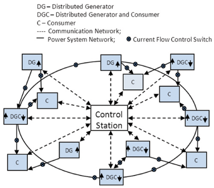
Figure 1: A conceptual architecture of distributed generator system
Electrical Noise in DGS
The DGS may contain both common mode and differential mode electrical noise. Both noise types conduct and radiate through electrical circuits and associated metallic structures. The common mode noise flow is in the same direction on the live power conductors but flows differentially with respect to the ground conductors. The differential mode noise on any two power conductors is equal in magnitude but the flow is in opposite direction. The power loop area is one of the primary factors that must be considered for deciding the radiated emissions levels. The large loop areas produce the greater radiation. For differential mode noise radiation, the loop area formed between live power conductors must be considered, while, for common mode radiation, the loop area formed between live power conductors and ground conductor must be considered. In un-terminated or open circuited transmission lines, the loop area is formed through the free space similar to a monopole antenna [5]. The electrical noise source could be either from the loads, the DGS, or from natural events (for example, lightning). The noise produced in consumer loads such as electronic and digital devices connected to a DGS are regulated by government agencies (such as FCC, EU and VCCI etc.,) and will not be discussed here. Some electrical noise sources typically found in power system are noted.
- Power sysem that contains non-sinusoidal voltages.
- Voltage fluctuations, dips and interrupts.
- Switchgear noise due to circuit opening and closing.
- Oscillatory transients.
- Power surges.
- Power Line Communication (PLC) noise.
- Ctorona, Gap discharge and arcing.
- Lightning.
The electrical noise spectrum from Items (1) through (5) above is typically lower than 100 MHz [6]. The PLC produces broad spectrum of noise [7, 8]. The noise spectrum will be based on a single channel data rate and bandwidth of the transmission. The corona, Gap discharge, arcing and lightning noise spectrum extends up to 2 GHz. However, for a typical lightning event, there is significant noise below 200 MHz. Similarly the corona, Gap discharge and arcing events have significant noise below 1000 MHz. The lightning surge frequency spectrum has been studied by several researchers and is indicated in the references [6, 9]. The Gap discharge and arcing frequency spectrum details will not be discussed here. The corona radiates a periodic broadband spectrum for prolonged periods. Therefore, it is one of the interference nuisances to RF devices. The corona radiation effects on the wireless system receiver sensitivity levels are discussed below.
Corona
Corona is due to accelerated partial ionization, breakdown or discharge of gas molecules or atoms between two conductive surfaces under the influence of high electric fields that could appear as a blue luminous glow with a current typically measured in microamperes [10]. The corona occurs between conductive surfaces where there is a large concentration of charges and at smaller distance from the reference electrode.
At its onset, the corona will be intermittent or pulsating, and if the field is further increased, the corona current reaches a steady state. When the electric field is increased further there will ultimately be a transient or steady state arcing or sparking occurrence with a sudden jump in current.
The arcing voltage is typically two to six times the corona voltage. The corona does not completely connect the conductive surfaces of electrodes, but arcing bridges the conductive surfaces of electrodes. The corona inception voltage is higher for longer gap distances. But the relationship depends on the dielectric constant, temperature, pressure, and other physical variations between the gap surfaces. The corona is a high impedance phenomena occurring at high voltage and lower current. Not all corona charges from one electrode reach the other. Some portion of charges escapes from the corona and is radiated. Therefore, corona is an interference nuisance to RF devices. The corona radiates a periodic broadband spectrum. A typical corona radiation pattern is shown in Figure 2. As shown in Figure 2, the corona noise period is two times per power cycle.

Figure 2: Radiated corona periodic broadband spectral distribution from single phase AC power
Radiated Corona Spectrum Measurement in a GHz Transverse Electromagnetic (GTEM) Cell
Corona frequency spectrum is a well understood subject. The corona itself can directly radiate RF energy without aid of an antenna. The corona frequency spectrum data presented in most publications do not isolate the radiations from the electrical support structure used for corona simulation. The electrical structure could act as an antenna or tuned element and alter the radiation characteristics of the corona stream. The corona streams direct radiation is measured and presented in this section in its isolated form.
The radiating frequency spectrum of a corona was investigated in a GTEM cell. The GTEM Cell is a frequency extended variant of the traditional Transverse Electromagnetic (TEM) cell. The GTEM Cell is a large tapered section coaxial stub with air dielectric and a characteristic impedance of 50 Ω. One end of the stub is a feeding point and the other end is terminated by a combination of non-inductive high power resistors and RF absorbers. When a radiating object is placed between the center plane and outer ground plane, the total radiated power is directly proportional to the power measured at the apex of the GTEM. The radiated power level varies as inverse of distance ‘d’ between center plane and bottom ground plane. The GTEM supports a frequency spectrum from DC to several GHz. A 25 cm long coaxial cable mounted in the GTEM was used for generating corona. The center conductor at one end of the coaxial cable was looped back closer to the outer metallic shield as shown in Figure 3. The approximate diameter of the loop was 2 cm. The gap between the tip of the center conductor and the metallic shield of the coaxial cable was approximately 2.5 mm. The loop was placed between the GTEM center plane and the bottom ground reference plane, approximately at the center. The diameter of the loop was small enough so that the radiation contribution due to the loop was negligible up to 1 GHz. Several broadband suppression ferrites were added to the coaxial cable to prevent the cable from acting as a monopole antenna. A high voltage single phase AC generator was connected to other end of coaxial cable through the GTEM bottom ground reference plane. For these tests, voltage input applied to the coaxial cable ranged approximately from 2 to 4.5 kV. The stream of produced corona was approximately perpendicular to center plane of GTEM. The loop was rotated in its upright position 360° to provide for highest emission angle. At this angle, the frequency spectrum was measured and plotted for 2.5 mm, 7.5 mm and 10 mm gaps for frequencies between 30 and 1000 MHz. The data plot is presented for 10 mm gap in Graph 1. This setup provides a source of directly radiated corona spectrum that is mostly unaffected by the electrical supporting structures or polluted by the ambient environment. The generated energy spectrum of directly radiated corona is therefore available for use experimentally to compare against other types of interfering signals as applied to real world systems.
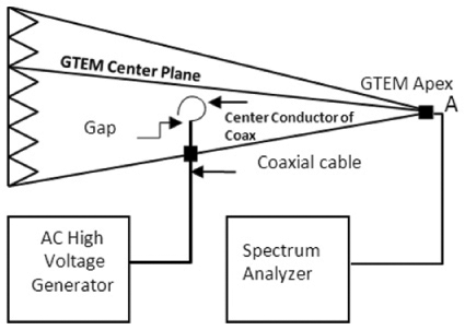
Figure 3: Test setup from measuring corona spectrum in GTEM cell

Graph 1: Radiated frequency spectrum of corona measured from a 10 mm gap
Radiated Corona Spectrum Measurement from 26 kV Substation
The radiated emission measurements from a local 26 kV/208V sub-station are presented in Graph 2. The measurements were made at an approximate 25 m horizontal distance from the radiating corona transmission conductors connected to string-insulators in the sub-station. The antenna and spectrum analyzers were located at an elevated location relative to the sub-station such that the radiating corona source from the sub-station was in line with the antenna. RF absorbers were placed on the sides and rear of the receive antenna to minimize the ambient noise. An investigative received power level measurement was made for both horizontal and vertical polarization using a broadband bi-log antenna. The received power levels were higher for the vertical polarization of the antenna and are therefore reflected in the plot. To maximize the received signal levels the antenna was moved 1 m distance horizontally and then vertically prior to recording the maximum levels. According to Friis transmission equation [11]
Pr/Pt = (λ/4πR)2Gor Got (1)
- Pr is power delivered to any load (Example: 50Ω receiver antenna port)
- Pt is power input to transmit antenna (in this case, it is part of corona stream power that is being radiated)
- Got is transmit antenna isotropic gain
- Gor is measurement antenna (Broadband bi-log) isotropic gain
- λ = free space wavelength of the measured frequency
- R = measurement distance
- (λ/4πR)2 is free space propagation loss(L) derived in Equation 3
The predicted effective isotropic received power level (Pr/Gor) in “dBm” at the measurement distance = (Analyzer reading in dBm – Gor in dBi ) (Pr/Gor) at any linear distance (R) between the radiating source and receive antenna = L (Pt Got) (2)
Graph 2 shows the measured noise power levels (Pr/Gor) in “dBm” for the frequency range from 30 to 1000 MHz. The measurements were made when corona illuminations were observed on certain parts of the conductor. The number of conductors and number of phases involved in corona illumination could not be accurately determined. The Graph indicates that radiation levels extend to 1000 MHz, but the power levels gradually decrease with increasing frequency.
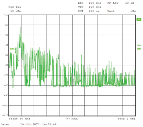
Graph 2: Radiated frequency spectrum of corona measured from a 26kV Substation at 25m distance
Corona Field Level Calculation at Closer Distance
Both Graphs 1 and 2 reveal the existence of a significant amount of radiated power up to 1000 MHz. Graph 2 indicates the measured received power level from the antenna near 1 GHz is -65 dBm at a 25 m distance. If it is assumed that the measuring instrumentation or control wireless transceiver for a DGS must be placed at 1 m distance from the transmission lines on a pole, the expected power level at the receive antenna port at 1 m distance can be calculated using the following Friis free space narrowband propagation path loss (L) equation. (Assuming that the path is clear of terrain or other objects and measurements are made in far-field.)
Free space propagation loss (L) = 20 log10 (Distance in meters) + 20 log10 (Frequency in MHz) – 27.56 dB (3)
Equation 3 is also successfully applied to broadband short distance propagation loss calculations [12]. The calculated loss (L) at 1000 MHz for 24 m is 60 dB Therefore, the field power at a 1 m distance from the corona producing transmission line is calculated to be -5.0 dBm The effective average field power will be based on the duty cycle of the noise which is the ratio of pulse width and pulse repetition rate.
For pulsed RF, the effective average power is 10 log10 (duty cycle). For 60 Hz power, the pulse repetition rate is 8.3 ms, but the corona noise pulse width for a given spectrum bandwidth is difficult to measure. The corona noise pulse width increases with AC field intensity (kV/cm) between the corona stream conductors. If a 1% duty cycle is assumed, then the effective received average power for the same setup at 1 m distance from the radiating source is -25 dBm.
In the absence of interfering noise, the modern wireless receivers using typical antenna are capable of processing signal levels lower than thermal noise levels (-114 dBm/MHz at room temperature). Therefore, the corona noise level is considered very high when compared to the sensitivity of a typical Cellular receiver which is approximately -120 dBm/MHz. This clearly demonstrates that corona radiation must be considered before planning any wireless communication system for controlling the DGS.
Wireless Communications System for DGS Control Functions
In-band noise is the primary concern for any wireless communication system. In-band noise degrades the ability of the communication system to receive low signal levels. There are no dedicated wireless frequency bands available for electrical power system controls. Either unlicensed or licensed bands must be used for wireless controls. The corona noise will affect both the unlicensed and licensed bands operating below 1000 MHz.
Although the modern wireless receivers are capable of functioning with the signal levels much lower than the noise levels, the overall signal to noise ratio is still important. For most data systems, after some noise threshold level is reached, the error rate will increase with increasing noise. The comparison of corona (noise) to signal frequency bandwidth and 1% error amplitude is as shown in Figure 4.

Figure 4: Corona noise level is higher than receiver sensitivity levels
Corona Noise and Cellular Base station Receiver Sensitivity
The minimum required signal-to-noise ratio (S/N) of wireless systems must be maintained in order to have a reliable communication link. The presence of increased in-band interference at the antenna receive port requires that the desired signal level must be increased to maintain the S/N ratio. The noise immunity levels are dependent on the wireless devices modulation techniques and receiver bandwidths. The noise immunity levels for the following modulation techniques were investigated using a 1900 MHz GSM Base Station, an 850 MHz CDMA Base Station and a 700 MHz LTE Base Station:
The test setup is shown in Figure 5. The receive port of the base station was tested with a continuous wave (CW), a fixed frequency modulated signal, a random frequency noise level and laboratory generated corona, and the processed demodulated signal was analyzed for data error. Since there are several variations in the operations of diversity ports, they were disengaged during the tests. The modulated signal was fixed at -90 dBm for all tests and no data error was noted at this level. The input noise power level was then increased until a 1% data error was observed.
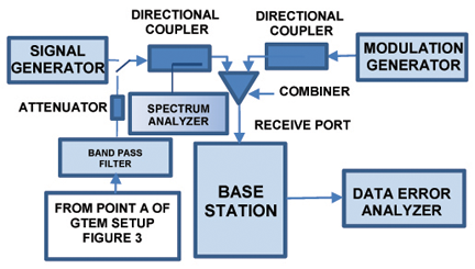
Figure 5: Base station receive port noise immunity test setup
The following input signals were used as noise:
- Continuous Wave (CW) signal
- 1 kHz 80% AM signal
- Random CW signal to sweep the receive frequency bandwidth at an 8 ms repetition rate. The AC corona noise spectrum repeats at every half power cycle of power (See Figure 2). For 60 Hz power the half cycle duration is 8.3 ms. Since 8.3 ms repetition rate signal was not available, an 8.0 ms repetition rate signal was used instead.
- GTEM generated corona noise at the receiver frequency bandwidth.
The noise signals (a) and (b) were applied at the center frequency of the receive channel. The noise immunity levels for 1% data error for different modulation technologies are shown in Table 1. Noise levels approximately 6 to 10 dB above 1% data error produce a sudden increase in data error (50 to 60% data error) rendering the system useless.
| Modulation Technology | Noise Source level above the signal level | |||
| CW dB | 1 kHz 80% AM dB | In-Band random CW at 8 ms repetition rate dB | In-Band corona from GTEM dB | |
| GSM (200 kHz) | 10 | 8 | 10 | ** |
| CDMA (1.25 MHz) | 20 | 18 | 20 | 15 |
| LTE (5 MHz) – QPSK | 42 | 42 | 40 | 34 |
| LTE (5 MHz) – 64 QAM | 37 | 37 | 37 | 32 |
| LTE (10 MHz) – 64 QAM | 40 | 40 | 40 | 34 |
Notes: ** Insufficient corona signal at 1900 MHz Table 1: Noise level in dB above the signal level for data error reaching approximately 1%
Table 1: Noise level in dB above the signal level for data error reaching approximately 1%
The wireless control stations for DGS will be installed at fixed locations. Therefore, the receiver operating range sensitivity levels can be fixed accounting for the anticipated noise levels and calculated link budget. The corona noise impact levels for a 1% data error are much higher than the signal levels. Therefore, implementation of a noise amplitude limiter circuit can solve the corona noise problems.
Conclusions
Mapping the land line communication along the power transmission lines for DGS communication and control is one of the major technical and economic challenges. Therefore, wireless should be a more viable alternate. The electrical power noises associated with corona, arcing and lightning will seriously degrade the communication and control frequency band spectrum usage. The immunity test results provided in Table 1 show that wireless system is more susceptible to corona spectrum than the CW or modulated CW signals. The noise levels will be severe, especially during extreme weather conditions when most power outages are likely to occur. This article establishes that Corona has a significant noise frequency spectrum up to 1 GHz. Published works show that extremely high voltage transmission lines produce corona noise up to 2 GHz [13]. For any frequency spectrum use for wireless communication below 2 GHz then special consideration should be provided as follows:
- Plan the link budget so that low sensitivity wireless communication devices may be employed.
- Consider use of broadband wireless communication systems for minimizing interference.
- Modulation techniques using OFDM (such as WiMax and LTE) are more secure and reliable compared to other modulation techniques.

References
- K. Budka et al., “GERI- Bell Labs Smart Grid Research Focus: Economic modeling, Networking, and security and Privacy”, 2010 IEEE International Conference on Smart Grid Communication”, pp 208-213.
- IEEE Std 2030, “IEEE Guide for Smart Grid Interoperability of Energy Technology and Information Technology Operation with the Electric Power System (EPS), End-Use Applications, and Loads, 2011, pp 6-13.
- T.M. Overman, R.W. Sackman, “High Assurance Smart Grid: Smart Grid Control Systems Communications Architecture”, 2010 IEEE International Conference on Smart Grid Communication”, pp19-24.
- M.Pavela, P.G.Murthy, “Transient Stability of Power Systems (Theory and practice)” John Wiley & Sons, 1994, pp 4.
- D. Moongilan, “Radiation characteristics of short unterminated transmission lines”, 2009 IEEE International Symposium on Electromagnetic Compatibility, pp 57 – 62.
- E. N. Skomal, A. A. Smith, Jr., “Measuring the radio frequency environment”, Van Nostrand Reinhold Company Inc., 1985 pp 305-311.
- S. Gali, A. Scaglione, Z. Wang “Power line communication and Smart Grid”, 2010 IEEE International Conference on Smart Grid Communication”, pp 303-308.
- M. Tanaka, “High frequency noise power spectrum, impedance and transmission loss of power Line in Japan on intra building power line power line communications”, IEEE Transactions on consumer Electronics, Vol. 34, No.2, May 1988 pp 321-326.
- C. Leteinturier, J. H. Hamelin, A. Eybert-Berard “Submicrosecond characteristics of lightning return-stroke currents.”, IEEE transaction on Electromagnetic Compatibility, Vol.33, No.4., November 1991, pp351 – 357.
- D. Moongilan, “Corona and arcing in power and RF devices” 2009 IEEE Symposium on PSES, pp 1-7
- C.A. Balanis “Antenna Theory Analysis and Design; 3rd Edition, John Wiley & Sons 2005, pp95
- H.R. Anderson, “Fixed Broadband Wireless System Design” John Wiley & Sons, 2003, pp 31
- W.E. Pakala, V.L. Chartier , “Radio noise measurements on overhead power lines from 2.4 to 800 kV,” IEEE Transactions on Power Apparatus and Systems, Vol. PAS-90, No.3, May/June 1971, pp. 1155 – 1165.
This article won the Symposium Best Paper Award at the 2012 IEEE International Symposium on Electromagnetic Compatibility in Pittsburg PA.
© 2012 IEEE. Reprinted, with permission, from the 2012 IEEE International Symposium on Electromagnetic Compatibility proceedings.
 |
Dheena Moongilan is a Distinguished Member of Technical Staff at Bell Laboratories of Alcatel-Lucent. He is a Principal EMC design Consultant for Alcatel-Lucent. He has published 20 formal IEEE papers on EMC and holds two US patents. He is a NARTE certified EMC Engineer and Master EMC Design Engineer. He holds a B. E. in electrical engineering and a M. S. E. E. from the College of Engineering at Madras University in Guindy, India, and M. S. E. E. computer engineering from the Illinois Institute of Technology in Chicago. |
