Nowadays, semiconductor technology requires that integrated circuits be interconnected at very high-speed data rates. Taking time domain measurements on the digital links can offer challenges for electronic engineers, one of which is to decide which is the better measurement instrument to use in the given signal integrity environment. The time domain reflectometer (TDR) and vector network analyzer (VNA) are the staple instruments to consider, each one having its pros and cons. Here we compare the responses of the two instruments when used for taking time domain measurements of typical signal integrity devices under test (DUTs): a stripline and a through hole on a FR-4 board.
Most electrical engineers agree that the TDR and VNA are the two different instruments in the labs which can be used for taking time domain measurements [1]. It appears that these two tools are not indiscriminately interchangeable due to the fact that TDR works in the time domain while the VNA functions in the frequency domain. However, the use of a fast Fourier transform (FFT) allows us to use either the two instruments for time and frequency domain measurements. Typically a digital or signal integrity (SI) engineer uses a TDR for taking time domain measurements due to its quick setup and easy to use. The microwave or radio frequency (RF) engineer instead prefers to use VNA for tacking measurements up to very high frequencies with good accuracy. It is of paramount importance to note that the current semiconductor technology develops digital chips interconnected at always increasing data rates in the gigahertz range, which means digital signals with very deep edges and very high content of frequencies. Consequently the job of a digital engineer gets closer and closer to that of a microwave engineer, and requires taking useful design information from both the time and frequency domain measurements. Considering that both the TDR and VNA are expensive instruments and sometimes a same lab cannot afford to buy both, the question is: “What is the better instrument for the needed time domain measurement?” In other words, say for a connector manufacturer using VNA: ‘”re the time domain measurements taken with a VNA comparable with the same measurements taken with a TDR?”.
So lets compare the time domain measurements taken with TDR and VNA on the same DUT [2], highlighting differences and similarities. Reflection coefficient (TDR) and S11 (VNA) measurements, taken on a 40”-long 50 Ω stripline laid out on o FR-4 board, are contrasted. Also, VNA step and impulse time domain responses of a 0.8 mm through hole on the same FR-4 board are compared.
Time Domain Reflectometer
The TDR is an instrument that operates in the time domain [2, 3]. It consists of a high speed oscilloscope with a sampling module to generate a voltage step. The voltage step propagates down the transmission line under investigation. The incident step and the reflected voltage waves are algebraically added and monitored by the oscilloscope at a particular point on the line (Figure 1).

Figure 1: TDR block diagram
The echo technique is used reveals at a glance the position and nature (resistive, inductive or capacitive) of each discontinuity along the line in terms of bumps and dips. A bump indicates a high-impedance event (e g., open, reduction in line-width, inductive discontinuity). A dip indicates a low-impedance event (e g., short, increase in line-width, capacitive discontinuity).
TDR measurement is not taken in absolute units, such as volt, but it is based on the ratio of reflected voltage to transmitted voltage, called the reflection coefficient.
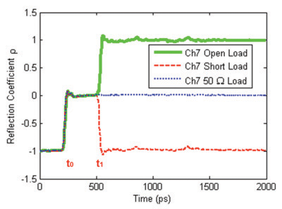
Figure 2 shows the typical TDR measurement in case of open, short, or 50 Ω loads. Note that the time interval t1 – t0 is the time from the TDR to the mismatch and back again.

Figure 2: TDR measurement
Vector Network Analyzer
The VNA measures the S-parameters of a RF or microwave device and displays the results in the frequency domain. It does everything a scalar analyzer does, adding the ability to measure the phase of a device over a great dynamic range and with more accuracy. The availability of the phase information allows the time domain feature.
An inverse FFT is used to convert the frequency domain to time domain. Note that the digital signal processing (DSP) technology, fundamental by computing error correction terms, permits implementation of a type of FFT known as a chirp Z transform.
The VNA uses two different time domain processing techniques: low pass and band pass.
The low pass technique requires a harmonically related set of frequencies that start at the lowest frequency possible and extrapolate a DC term that provides a phase reference so that the true nature of a discontinuity can be seen. It allows two presentations: step response or impulse response. A step response is the integral of the impulse response and displays the discontinuities as would a TDR.
The band pass technique does not use phase reference, so vector information is lost; only magnitude information is available. This type of processing is common in fault location for testing transmission lines
It is important to consider that the VNA uses windowing to condition data prior to time domain transformation. The window is a curve derived from a mathematical function used to mitigate edge effects associated with a finite data set in the FFT.
Measurement Examples
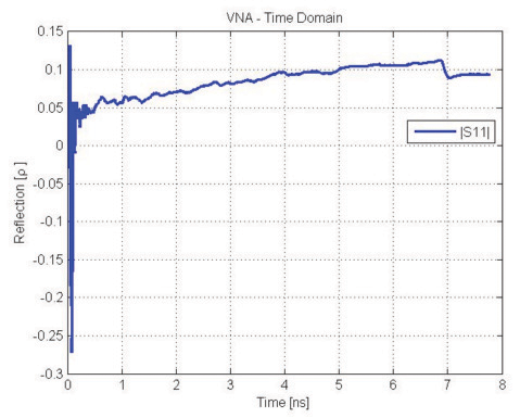
Figures 3 and 4 compare the measurements taken with a TDR and a VNA on a matched 4” long 50 Ω stripline laid out on a FR-4 board.

Figure 3: Stripline measurement taken with a TDR

Figure 4: Stripline measurement taken with a VNA
The incident step of the TDR being used has a rise time equal to 20 ps.
The VNA being used has a frequency span from 0.04 GHz to 40 GHz. It considers a low pass technique with step response and a nominal window.
As is shown, the two measurements are quite similar. Note that the length in nanaseconds for the stripline in Figure 3 is double with respect to the same length in Figure 4. This is due to the fact that the TDR (Figure 3) measures the round trip delay of the step propagating along the stripline, which is the time from the TDR to the mismatch (the end of the line) and back again.
Both the measurements show an upward trend of the measured reflection coefficient due to the frequency dependence of the characteristic impedance of the line [4].
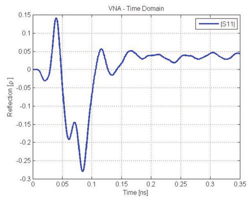
To confirm the equivalence of the two instruments in the time domain, the discontinuity due to the input SMA connector of the stripline has been displayed on the TDR and VNA (Figures 5 and 6). Note the capacitive behavior of the connector.

Figure 5: Input SMA of the stripline displayed on the TDR

Figure 6: Input SMA of the stripline displayed on the VNA
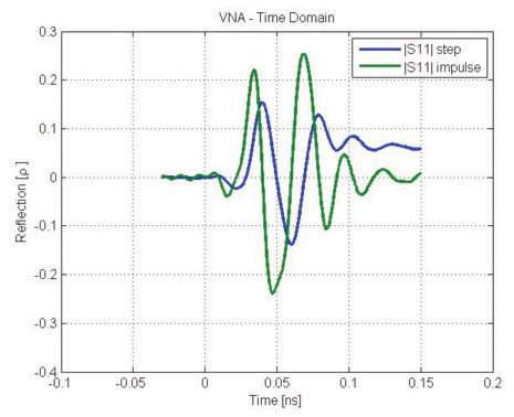
Figure 7 shows the two responses (step and impulse) used in the low pass processing technique, illustrating the relationship between them. The step response is the integral of the impulse response.

Figure 7: VNA step and impulse responses
The two responses are used for displaying the discontinuity due to a plated through hole (drill: 0.8 mm) with annular ring of 1.2 mm, laid out an a FR-4 board 1.6 mm thick.

Figure 8: Step and impulse responses of a through hole displayed on the VNA
Conclusions
After comparison of time domain measurements taken with a time domain reflectometer (TDR) and a vector network analyzer (VNA), it seems that the operator’s background is the deciding factor in which tool is best for the job. The TDR goal is temporal analysis. This means quick setup, intuitive controls, and results oriented operation. In contrast, the VNA excels in frequency domain analysis. The data measurements are extremely stable, precise and versatile. However, the VNA also needs calibration and must use FFT for taking time domain measurements. The measurement uncertainty of the VNA is an order of magnitude below that of the TDR. Both the instruments provide equivalent information in the time domain and their use depends on the ability of the engineers and their preferences. And, if lab resources are limited, only one instrument is necessary. ![]()
References
- P. Pino, ”Comparison of VNA and TDR Measurement Uncertainty Using Coaxial Cables”, Microwave Journal, March 2010.
- V. Ricchiuti, “Time and Frequency Domain Measurements for SI”, EMC Europe 2012, September 12-21, 2012, Roma, Italy.
- V. Ricchiuti, “Checking High Speed Digital Backplane”, 2012 IEEE Electromagnetic Compatibility Magazine, volume 1, quarter 2.
- S. Caniggia, F. Maradei, “Signal Integrity and Radiated Emissions of High-Speed Digital Systems”, 2008 John Wiley & Sons.
 |
VITTORIO RICCIUTI joined Italtel and Siemens R&D lab after he received the degree in Electronic Engineering from the University of Pisa in 1989. He gained wide experience in the field of very high speed data transmission and EMC. He then joined Compel Group and his main research activities included: noise reduction in PCB, high speed links characterization and measurements. He is now is responsible for the R&D lab of CPE Group, involved in the design of all types of interconnection systems, optical and electrical. He can be reached at ricchiuti@cpeitalia.it. |
