A method of determining the performance of an open area test site (OATS) or an anechoic chamber is to perform a site attenuation measurement. The process used is to step a signal source at the transmitting antenna and use a receiver or spectrum analyzer at the receiving antenna. The two are stepped together to give a set of data that shows the performance of the test site or chamber. ANSI C63.4 outlines the process for performing normalized site attenuation (NSA) measurements. In these measurements, the spectrum analyzer controls the signal source.
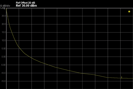
The design of today’s anechoic chamber is aimed at emulating open area test sites. Performance in the chamber is evaluated using two antennas, a receiver or spectrum analyzer and a signal source. The measurements are made in two steps. First the cable connecting the source to the transmit antenna is connected to the cable that connects the signal analyzer to the receive antenna and a series of values are measured by stepping the source and receiver or signal analyzer in ~10% steps. The through-line measurement is referred to as Vdirect and the measurement made using the antenna is called Vsite. ANSI requires that a chamber must be within +/- 4dB of the ideal site attenuation. In ANSI C63.4, the ideal normalized site attenuate is shown in tabular form. The graph in Figure 1 shows the ideal normalized site attenuation measurement. The formula for performing site attenuation measurements is AN = VDirect – VSite – AFR – AFT – ∆AFTOT. ∆AFTOT is assumed to be 0 at a 10 meter distance from receive to transmit antenna.

Figure 1: Theoretical normalized site attenuation 30 MHz to 1 GHz.
With the receiver controlling the external source the measurement system can be swept over the entire range of interest. The max hold feature of the receiver allows the recording of the highest level signals. In order to obtain a graph of the chamber or OATS true performance, the receiving antenna must be swept from one meter to four meter height. The loss of the two antennas must be removed from the measurement and the result is normalized to the direct measurement.
Updated Approach to Site Attenuation Measurements
Since the signal source is separate from the receiver, unlike signal analyzers that have a built-in tracking generator, the source can be placed near the transmit antenna to reduce cable loss, thereby improving the signal to noise performance of the measurement. Also, the cables that are connected as a through-line are shorter, reducing cable lose. Once the level of the through-line is established and placed into the trace for normalization, the cables can be connected to the two antennas that are placed at 10 meters apart. Figure 2 shows the typical interconnection between the source and the EMI receiver.

Figure 2: Typical external source control layout
The transmit center of the antenna is fixed at one meter above the ground plane. The receive antenna is moved from 1 meter to 4 meters above the ground plane. At the same time, the signal source and EMI receiver is swept over the frequency range that the antennas are designed for and calibrated over. It is important that the antennas are calibrated correctly, that is, the calibrated antenna factors completed by the manufacture are very close to the actual relationship between the field at the plane of the antenna and the voltage out of the antenna that the antenna experiences at a specific frequency. If this is not, the case then the actual normalized site attenuation calculation may not be close to the theoretical site attenuation. In order to pass the normalized site attenuation, the measured values must fall within +/- 4 dB of the theoretical site attenuation.
In order to use an external source located at a distance to the EMI receiver, some connections need to be made. First, the frequency references need to be tied together to insure frequency tracking. Communication between the source and the receiver can be accomplished using USB, GPIB or LAN. In this case we will use LAN. Communication between the source and receiver includes start/stop frequency and amplitude levels. The other connections can include triggering to insure that the source and receiver step together over the frequency range.
The next consideration is the resolution bandwidth to be used for the test. It is important that there are no gaps in the data collection. If the bandwidth is narrower than the step size of the frequency steps, then dropouts or signal spikes can be missed. The total number of steps used in this case is 1601.
Correcting for Antenna Factors
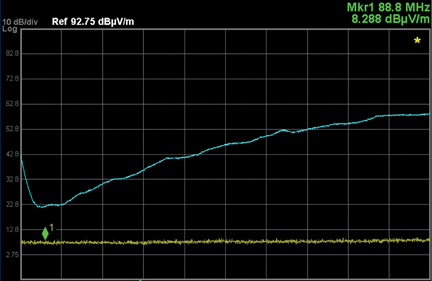
Modern signal analyzers or EMI receivers are able to compensate for the response of broadband antennas. Antenna manufacturers send the calibration data for the antennas which are then loaded into a correction factor editor. Since the site attenuation measurements require two antennas, the easiest way to correct for both antennas is to add the corrections together and place it into the corrections editor. The typical correction for a broadband antenna ranges between 7 dB and 25 dB. Adding the two together gives a correction of 14 dB to 50 dB. In order to meet site attenuation requirements, antennas to be used must have the corrections as accurately characterized as possible. A trace showing only the correction factor for the combination of the antennas is shown in Figure 3. The corrected noise floor is the antenna factors added to the noise floor.

Figure 3: The yellow line is the noise floor and blue line is the noise floor corrected for both antennas
With the antennas in the horizontal polarization, sweep the antenna tower between 1 meter and 4 meters with the signal analyzer or EMI receiver in the max hold trace configuration. The result is a corrected trace that shows the site attenuation over the frequency range of interest.
Choosing the Bandwidth
There is a trade-off between the number of data points, sensitivity and dynamic range. Choosing the correct bandwidth can help solve some of the issues. In order to avoid missing spikes and dropouts of signals, it is recommended that the bandwidth be at least 200 kHz, because the maximum number of points is 1601 when using an external source. The minimum bandwidth step size would be 168 kHz to allow a bandwidth per point. The video bandwidth should be equal or greater than the resolution bandwidth.
Normalizing to a Through-line Measurement
The cable connected to the transmit antenna and the cable connected to the receive antenna are connected together with a high quality barrel connector (very low loss) and the frequency responses of the two cables are measured using the combination of the external source and the receiver. The amplitude values versus frequency are subtracted from the corrected values of the site measurements when using the antennas.
Normalized Site Attenuation Limits
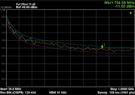
In Figure 4, a continuous plot of the theoretical normalized site attenuation is displayed. The limit as stated earlier was +/- 4 dB. A linear plot of the limits is shown. The goal in the swept tune NSA is to have all the values fall within the limit shown.

Figure 4: NSA limits
Performing Site Measurements
Now that the antennas are in place and the source frequency range is set correctly for the broadband antennas used, the measurement can be started. The antennas are placed in the horizontal position. The receive antenna is moved slowly from 1 meter to 4 meters. The source/receiver combination is swept much faster than the antenna is moved so that at least 20 sweeps are taken while the antenna is moved though its range. The trace mod is maximum hold so that only the highest values are maintained on the display. These maximum values relates to the highest signal strength received by the receiving antenna. These maximum values are a result of the combination of the reflected and line-of-sight signals. The theoretical normalized site attenuation measurements take into account the reflections from the ground plane. What the theoretical NSA does not take into account are the reflections from absorber lined areas such as the ceiling or the back walls.
An open area test site usually does not have these additional reflective problems unless there is a reflective surface within the area that may influence the overall measurements. One of the open area test sites that I was involved with had a cyclone fence 50 yards off the center line, which did affect the measurements. When the fence was moving in the wind we did see a couple of tenths of a dB change.
Dealing with the Trace Data
Let’s analyze the trace that is on the display after the maximum signals have been captured. Since the data was captured in a chamber, there are no large ambient signals to obscure the measured data. The first item to note is that the data is corrected for the loss of the two antennas used for the measurement. An important point to note is that the correction factors used for the antennas must be as accurate as possible. One or two dB of error in the correction factors will cause the same level of errors in the site attenuation measurement.
The trace data was stored as a .csv file and then displayed on the results shown in Figure 5. The .csv file allows closer inspection of individual frequency points.

Figure 5: Final results of normalized trace data
Once the normalization is performed, the errors will be removed since the systematic errors are in both the site attenuation measurements and through-line measurement. None systematic errors, such as thermal drift and some aging phenomenon, are not removed through normalization. However, allowing the source and receiver to warm up and stabilize will greatly reduce non systematic errors.
Comparison to Theoretical Site Attenuation Measurements
Since the theoretical attenuation for an ideal site is a group of fixed-frequency data points, another plot was made using those fixed frequency plot points. The data is from a ten meter chamber. The power of the source driving the transmit antenna was adjusted so that the loss in the higher frequencies is still above the correction factor for both antennas. As an example, the total corrections of the two antennas at 900 MHz is 49.8 dB and the theoretical normalized site attenuation is -12.8 dB. The overall power needs to be high enough to be above the corrected noise floor to get an accurate amplitude reading without added noise to the measured signal.
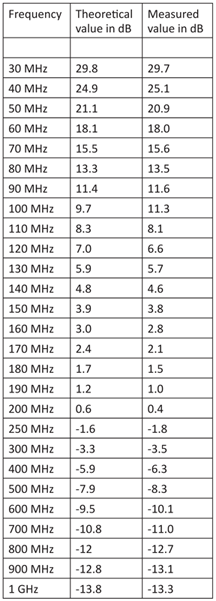
The signals in the plot in Figure 6 were measured using the marker function and placed in Table 1. The digital IF of the signal analyzer or EMI receiver allows the user to measure signal anywhere on the screen without compromising accuracy, even signals that are off the top of the display are measured accurately.

Figure 6: Measured fixed frequency points as described in ANSI C63.4

Table 1: Fixed frequency theoretical NSA versus measured values
Site Attenuation Measurements Above 1 GHz
The above discussion focused on site attenuation measurements from 30 to 1 GHz. As the testing moves higher in frequency, it is even more important to have the signal source and receiver as close to the antennas as possible because of signal attenuation in cabling. If amplifiers are used to improve performance at these higher frequencies, they also must be included in the overall loss/gain profile. The amplifier gain versus frequency must be well understood. This characterization can be accomplished using a network analyzer. Use the external source applied for site attenuation to characterize the amplifiers and associated cabling, and place the results in correction factor arrays, available in most EMI receivers or signal analyzers.
Summary
The use of an external signal source controlled by a signal analyzer will greatly improve the process of performing site attenuation measurements. Shorter cables reduces signal loss because the source is at the transmit antenna, which is increasingly important as the test frequencies go higher. The frequency and the amplitude of the source can be controlled by the signal analyzer. It is very important to set the ideal signal level to perform site attenuation measurements over the desired frequency range. As seen before, there is a trade-off between noise floor, signal level and bandwidth. The total number of data points must be considered to establish the needed overlap between steps or points. I recommend that the signal level be at least 8 to 10 dB above the indicated noise, which means adjustment of bandwidth/signal level to avoid overloading the input mixer of the receiver or signal analyzer. ![]()
 |
Dennis Handlon is currently a product manager at Agilent Technologies, Inc. signal analysis division. He specializes in electromagnetic interference measurements using the new EMI measurement receiver. Dennis has been involved with the EMC community as an IEEE member since 1990. Prior to EMC he was the product manager for millimeter frequency measurement products. Dennis has a BSEE from San Jose State University. |
