The mirror technique is a very old technique to be used with PCBs when failing in radiated EMC tests. An easy solution to avoid changes in layout if the technique can be applied to your product.
I have been using the mirror technique (or image plane technique) [1] from many years ago. It is easy and gives you a lot of information about the sources of your radiated emissions.
The technique is especially useful if you are not in a position to change layout or redesign the circuit, typical in troubleshooting scenarios.
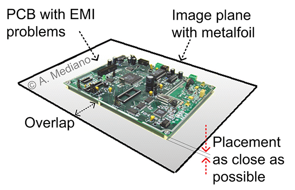
To implement it, a metallic plane is placed beneath the culprit PCB as close as possible to its underside with a larger size so as to overlap the edges as shown in Figure 1. If you have no problems with cables attached to the PCB it is not necessary to connect ground of the circuit to the metal plane. No other special consideration is needed.

The result is a reduction in the radiated profile of the prototype and the idea works with or without cables attached to the PCB.
The effect of the metal plane is to create a mirror electromagnetic effect so an image of your PCB is created as in Figure 2.

Consider for example a PCB where currents iEMI create radiated fields H1 in point P (Figure 3a).

Those currents in PCB traces (both differential and common mode), create induced currents on the metal plane (Figure 3b) so radiated fields on point P because iEMI (H1)and inducted currents (H2) tend to cancel: H1=H2 and opposite.
The mirror model is shown in Figure 3c, where the equivalent image currents (flowing in the opposite direction of the original PCB current) of the metal plane are equivalent to currents from the PCB image.
If you have problems radiating with cables attached to the PCB, signal and GND wires from that cable must be connected to the image plane: signal wires through a small RF capacitor and ground wires directly and at the same point where the wire is connected to the PCB.
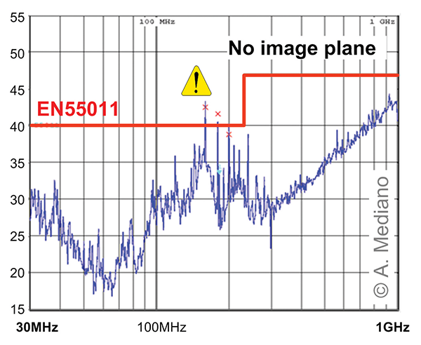
A real world example is included to show the advantages of the image plane method where radiated emissions from a commercial product (with digital and RF technology) were measured in a semi anechoic chamber. The product was located 1.0m above the ground plane, on a wood table and 3.0m away from the receiving antenna (Figure 4).

Special activity was found in the 110-250MHz range (harmonics from digital circuit) failing to comply with CISPR limits but emissions were not from the power supply cable (a typical antenna for this frequency range). The board was a large two layer board with the possibility to radiate in that frequency range.
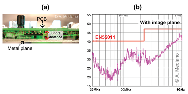
To reduce the emissions, an image plane was placed beneath and close (h<5mm) to the main PCB. The plane was not electrically connected to the PCB (Figure 5a).
As predicted, the image plane caused a considerable 8-10dB reduction in radiated emissions (Figure 5b) without any other change.

The technique is really useful for one and two layer boards and you can use it to confirm that a ground plane in a new prototype will be a good solution for future versions of the product (as in the case of our example).
Reference
- R. F. German, H. W. Ott and C. R. Paul, “Effect of an image plane on printed circuit board radiation”, IEEE International Symposium on Electromagnetic Compatibility, Washington, DC, 1990, pp. 284-291.
 Arturo Mediano received his M.Sc. (1990) and his Ph. D. (1997) in Electrical Engineering from University of Zaragoza (Spain), where he has held a teaching professorship in EMI/EMC/RF/SI from 1992. From 1990, he has been involved in R&D projects in EMI/EMC/SI/RF fields for communications, industry and scientific/medical applications with a solid experience in training, consultancy and troubleshooting for companies in Spain, USA, Switzerland, France, UK, Italy, Belgium, Germany, Canada, The Netherlands, Portugal, and Singapore. He is the founder of The HF-Magic Lab®, a specialized laboratory for design, diagnostic, troubleshooting, and training in the EMI/EMC/SI and RF fields at I3A (University of Zaragoza), and from 2011, he is instructor for Besser Associates (CA, USA) offering public and on site courses in EMI/EMC/SI/RF subjects through the USA, especially in Silicon Valley/San Francisco Bay Area. He is Senior Member of the IEEE, active member from 1999 (Chair 2013-2016) of the MTT-17 (HF/VHF/UHF) Technical Committee of the Microwave Theory and Techniques Society and member of the Electromagnetic Compatibility Society. Arturo can be reached at a.mediano@ieee.org. Web: www.cartoontronics.com.

