 Reading EMI test results from a test lab is very much like a radiologist reading a CT scan or MRI results. To the novice, it may seem very hard to decipher what is what, but to the trained eye, the test results provide a road map to not only the frequencies of the outages, but also an indication of what or where the outages more than likely are emanating from.
The engineering analysis process regarding the test scans or test results should be as follows:
- Evaluate the magnitude and nature of the problem. In this process we measure the frequency and the magnitude of each peak in the areas of the outages. It is important to realize that many of the outage peaks are not something you necessarily have to worry about as they could simply be harmonics of the key problem frequency. For instance, if you have noise peaks at 75 MHz, 150 MHz, 225 MHz, 300 MHz… these are obviously harmonics associated with the same problem frequency.
- Use hand held near field E and H field probes to perform sniff testing to determine the specific source or sources of the issues. Specifically, we look for measured frequencies outages as documented above. A near field probe allows us to identify not only the frequency of the RFI noise, but also to identify the location where the noise is predominantly coming from.
- Analyze the design of the Unit Under Test (UUT) in conjunction with the initial scan and sniff test results. This helps to determine the next course of action. We look at the electrical design of the UUT to establish if the frequencies of concern used. For example, is there a clock or other frequency source that aligns with the measured outages?
- EMI Failures or out of limit conditions are typically attributed to grounding issues, lack of adequate shielding, need for proper EMI filtering or poor PCB layout and design practices.
- To help illustrate how to read these testing results, here are a couple of real world examples that will help you understand how to go about analyzing what the test data is actually telling you.
Case Study #1
Test Results: Failed CE102
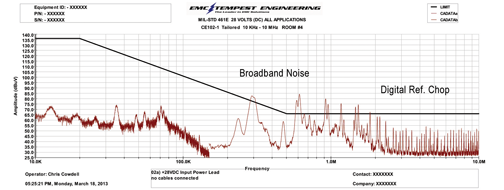
We measured and verified the Test House initial results. (Figure 1)

Figure 1
The EMI/EMC design change: A system had significant RF Noise that was primarily caused by poor grounding methods and switching power supplies which are typically noisy devices. The noise was primarily in the low frequency between 300 KHz and 3 MHz.
- We analyzed the grounding of the system and helped isolate the grounds so that the grounds did not re-inject noise into the electrical system. Based on the measured noise, we believed that the broadband noise and digital chop were a result of inadequate grounding as well as coupled noise from the switching power supply. Please note the harmonics in the measured data above, were at 300 KHz, 600 KHz, 900 KHz etc.
- Next, we separated the digital, signal and power grounds, and tied them together through an RF wire wound choke to provide the same ground reference, but not the ¼ wave intrusion. This allowed for isolation of the RF noise source while reducing the cross contamination of the grounds. As we like to say,
- “A ground is not a ground, even if it is labeled so!”
- We then reviewed the system’s interface requirements and found the simplest solution was to add filtering to the existing connector. It was decided that we would add ferrite materials to help reduce the low frequency noise components as well as using capacitive filtering to reduce the noise. These were built into the existing connector harness. Type 43 material ferrites were introduced on each pin and a type 31 material core was added to the harness in addition to adding 47,000 pF caps to each pin (The most we could build into the tightly spaced connector in a short period of time.) Type 43 ferrites are made of NiZn and are mostly used for suppression of conducted EMI from 20 MHz to 250 MHz, while type 31 ferrites are made of MnZn and are specifically used for EMI suppression applications from as low as 1 MHz up to 500 MHz.
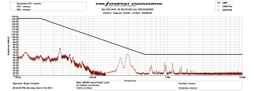
- The System was then retested with the modified grounding scheme and with the custom filtered connector utilizing chip capacitor filtering in conjunction with a large inductive choke. (Figure 2)
- These fixes solved the system’s EMI issues and allowed it to pass EMI/EMC compliance testing as in Figure 3.

Figure 2

Figure 3
Final Test results (PASS)
Case Study #2
Test Results: Test Unit, Passed CE101, Failed CE102 (+9dB exception), Passed RE101, and Passed RE102
After performing the CE102 test as well as using a near field probe to identify the source of the EMI outages, we concluded that the following critical factors were contributing to the CE102 Failure:
- The design utilized a noisy switching power supply
- The positioning of the power supply directly underneath the PCB’s digital section The noise from the switching supply was radiating directly to the signal lines on the PCB.
- Improper AC neutral terminations to the chassis AC neutral was directly tied to the chassis which was also tied to –VDC. This caused noise to be re-injected back into the digital circuits from the AC power system. Note the noise on the AC neutral and how this noise followed the noise on the hot lead but extended into the higher frequency range.
- Lack of proper EMI filtering on the input AC power lines, and the lack of EMI (LC) filtering on the output lines of the power supply to the PCB lead to the conducted emissions failures.
As a result of this analysis, we made the following fixes:
- Modified location of electronic items within the unit and provided some shielding where we could not relocate items. By relocating the source of the noise to further away from the data cables to the PCB, we reduced the effective coupling of the noise to the cables and thereby reduced the system noise.
- Changed the power supply used in this design from a switching supply to a linear supply.
- Modified system grounding and bonding to eliminate tying grounds together without some isolation of noise. We tied the AC neutral to the chassis through an RF choke to provide the logical ground connection, but protecting the digital ground from the noise inherent in the AC power.
- Added EMI filtering at the interface connectors to eliminate the noise. Filtering at the interface is the best location to eliminate incoming and outgoing noise.
Results: Unit Passed CE102 testing

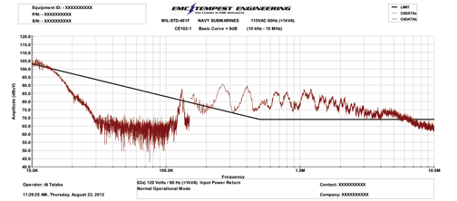
Figure 4: CE102-1 (+9dB) 115VAC Hot Lead 60 Hz

Figure 5: CE102 -2 (+9dB) 115VAC Neutral Lead 60 Hz

Figure 6: CE102-2 (all 4 Antennas combined)
Summary
The majority of the failures are attributed to a few key items:
- Poor grounding design and implementation (combining analog, digital and “other grounds”)
- Poorly selected power supplies and modules
- Improper shielding methods
- Poor PCB layout and design techniques for EMI/EMC
- Insufficient filtering methods
Poor Grounding Design and Implementation
Many times we see poor grounding/ ferrite usage techniques, which allow RF noise to bloom from one part of a system and be dumped into another through the interconnection of grounds such as mixing AC and DC (returns) grounds. Most PCB designs have ground bounce to some degree. When designs interconnect various grounds such as digital, analog and even AC neutral, this causes significant noise issues in the overall design, making each ground fight to take control1 of the PCB.
Poorly Selected Power Supplies and Modules
Linear vs. Switched?
The other significant source of failures in EMI testing is the use of inexpensive and typically non-compliant switching power supplies. Switching supplies are widely used but are typically very noisy items. Linear supplies are better with regards to EMI but more expensive. Many power supplies come with filter modules, but they rarely provide sufficient filtering or adequate grounding to help resolve the EMI issues.
Improper Shielding Methods
System shielding should be designed into the original product design. Ideally all designs would incorporate a Faraday Cage design approach which provides a circumferential shielding layer encapsulating the electronics. Shielding can easily be added in some areas after determining that noise is emanating from that specific area.
Poor PCB Layout and Design Techniques for EMI/EMC
PCBs should always be designed with 4-8 layers or more. Two layer PCBs are not considered multi-layer and should be avoided in acceptable EMI designs. Do not mix or use common grounds within a PCB. Use whole ground planes and not segmented or islands of grounds within a plane in a PCB. Also avoid only using ground bus lines and not ground planes.
Basic PCB layering techniques must be adhered to including line spacing, awareness of adjacent signals for possible interference, right angle traces or knees. Additionally, designers must understand capacitance versus frequency to help solve your EMI compliance issues. All capacitors do not behave the same. Capacitors should be tuned to provide maximum filtering performance in the frequencies that are at issue. The lower the frequency at issue, the higher the required capacitance. Do not simply use 1 uF caps for all applications.
Insufficient EMI Filtering Methods
Though sometimes expensive, it is wise to at least consider designing your system with the inclusion of filtered connectors to provide you with the additional insertion loss, EM mitigation needed at the interface to the system to allow you to pass your EMI testing requirements. There are many types of filtered connectors and these can be planned on as a fall back as needed. EMI filter Inserts can also be used during testing to evaluate the potential benefits of filtered connectors.
Filter inserts are a simple low cost options which can be quickly installed, adding capacitive filtering to a unit under test to evaluate the feasibility of improving the EMI design with added filtering. These filter inserts are chip capacitor filters which can be quickly pressed into a connector to provide 40+ dB of insertion loss in a fairly narrow frequency range. They can be tailored to allow for different capacitances on each pin to address the different data frequencies transmitted on each pin. This helps eliminate as much noise as possible with these filter inserts. Filter inserts do not provide the broad band filtering that some systems will require, however they can still be used to evaluate the potential improvement that can be achieved through the addition of filtering.
Once filtering has been proven to be effective, the system can be redesigned to incorporate on board filtering, or filtering can simply be added at the interface in the connectors. Filtered connector solutions range from the chip capacitor level of filtering (40 dB) to Pi filtering (80 dB) which provides broader frequency performance and higher level filtering.
Additionally, ferrite materials can be added to help absorb system noise. Ferrite materials prevent interference from being transmitted in both directions; from a device or to a device (culprit vs. victim). Ferrite materials added to systems are used as inductors to form a passive low-pass filter. A pure inductor does not dissipate energy, but produces reactance that impedes the flow of higher frequency signals. A ferrite core or bead can be added to an inductor to improve its ability to block unwanted high frequency noise. The ferrite basically filters out the noise by absorbing the RF energy associated with the noise. This energy is dissipated out in the form of heat.
In summation, good EMI designs incorporate many basic concepts to improve the probability that the developed system will meet EMI testing requirements. Pre-compliance or pre-certification testing is a great way to fine tune and modify designs to help insure success when performing Final EMI testing. Pre-certification testing also provides you with an opportunity to try various design fixes and solutions without the pressure of final test certification to play with and implement simple design modifications to help your system ultimately pass EMI testing requirements. ![]()
References
- King, Phil. 2003. “Ground Bounce Basics and Best Practices.” Agilent Technologies. http://www.home.agilent.com
- Barow, Jeff. “Reducing Ground Bounce in DC-to-DC Converters—Some Grounding Essentials.” Analog Dialog. Volume 23, Number 3, pp. 7-9. http://www.analog.com/analogdialogue
 |
Robert Ydens Bob is the President and Founder of EMI Solutions Inc., in Irvine, California. Bob has a BSEE degree from the University of New Mexico and has worked in the EMI/EMC field for over 20 years. He started EMI Solutions 18 years ago when he left TRW where he worked on various programs from Space based satellites to Air Force and Army ground communications systems. He has worked on EMI Filter designs and EMI related Issues for the past 20 years and is considered a leading expert in the field of EMI filtered connectors. Bob resides in Trabuco Canyon with his wife and three children. He enjoys snow skiing, fishing, and coaching his children in volleyball and track and field. |
 |
Brett D Robinson Brett D Robinson, PhD is President and Chief Consultant of Robinson’s Enterprises, an established engineering consulting firm founded in 1995. Dr. Robinson also held the position of Director of Engineering for EMI Solutions from 2004-2014 and has worked as an Engineer for: General Dynamics, Northrup Grumman, Hughes Aircraft, Teledyne, GE Aerospace, Boeing, Isothermal Systems Research, United Defense, Navcom, John Deere, Smiths Aerospace, ISIS, United Defense, CASA, AGUSTA, COI, and Rogerson Kratos. With well over 30 years of experience, Dr. Robinson has built a client base that runs from commercial avionics, medical, computer based, automotive, communications, military, aerospace, along with international based companies. His consulting firm, Robinson’s Enterprises incorporates “Real Time, Hands On” experience and understands that electronic component sales depend upon product compliance with FAA, FCC, Military, CE, and SAE standards on a first time test pass basis. |
