Electrostatic discharge (ESD) design rules verification has grown in volume and complexity as integrated circuit (IC) designs have become more complex and added significantly more power domains. With each additional power domain, verification of the signals that cross these domains becomes more difficult (particularly in the identification of inadvertent paths), as well as the check of interactions between circuit blocks that may result in many potential ESD discharge current paths [1]. While not strictly related to ESD, designs that incorporate multiple power domain checks are particularly susceptible to subtle design errors that are difficult to identify in the simulation space or with traditional PV techniques. Often, these subtle reliability errors don’t result in immediate part failure, but in performance degradation over time. Effects such as negative bias temperature instability (NBTI) can lead to the threshold voltage of the PMOS transistors increasing over time, resulting in reduced switching speeds for logic gates [2-4]. At the same time, hot carrier injection (HCI), which alters the threshold voltage of NMOS devices over time [5], and soft breakdown (SBD) [5] also contribute as time-dependent failure mechanisms, adding to the degradation effects of gate oxide breakdown.
ESD rules for ICs with multiple power domains, IP reuse, and system integration require greater complexity to avoid device damage. Design hierarchy also comes into play where some rules are applied on a top cell and/or top pads, but others are applied between internal blocks that cross multiple power domains. Tracking the rules and the nets to which they apply is by no means a trivial task when performed manually. Automation is necessary to effectively and efficiently cope with these requirements.
As a result, multiple methods have been developed using modeling or simulation to perform chip-level ESD verification [6-8]. However, while simulation-based ESD verification methods, to verify compliance to human body model (HBM) and charged device model (CDM) requirements, are effective, they do not necessarily check all elements in the design for ESD violations. In particular, internal interfaces between different supply domains are not explicitly checked. Additionally, getting device models for simulation at these extreme conditions is often problematic.
Part 1 of this series, “Outlining the Essential requirements of the ESD Verification Flow”, provided an overview of the essential requirements of an effective ESD EDA verification flow [14]. This article (Part 2) discusses a well-established topological methodology for checking ESD design rules. The ESDA Technical Report 18, “ESD Electronic Design Automation Checks” (TR18) [13], provides an overview of recommended ESD checks that should be performed to validate appropriate ESD protection structures within a design. We will focus our effort on TR18 rule 5.1.3, which applies to internal interfaces between power or ground domains, a requirement that has been recently highlighted [9-11]. Rather than modeling or simulating, the methodology uses the device netlist topology to check all domain crossing interfaces and associated ESD devices in the entire design, and is realized using the Calibre® PERC™ tool from Mentor Graphics. Although internal interfaces may span many levels in the design hierarchy, checking is done hierarchically by utilizing a novel technique for topology-aware verification. In addition to performing topology checking, at times there is the need to include both topology and physical information to create a more comprehensive checking environment. Such an environment is required to perform ESD layout verification checks [12].
The following sections cover the targeted ESD rules, the new hierarchical algorithm, ESD rule variations. and verification results.
The ESD Rule
Transistors’ gates can be exposed to direct ESD events. This is particularly common in input receivers, although many other topologies can expose a gate oxide to an ESD discharge path. Since gate oxides (by virtue of their small capacitance) cannot shunt any significant amount of current, they have to be considered voltage pulse driven as far as their failure mechanism is concerned. It is irrelevant whether the gate oxide is connected to signal, ground, or supply. The failure criteria will depend on the actual combination exercised and whether a soft vs. hard oxide breakdown sets the failure limit (application-dependent) [13].
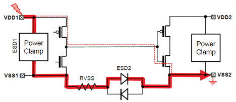
ESDA TR18, check 5.1.3 [13] is intended to verify presence of protections on signals that cross a power domain boundary. As shown in Figure 1, when the pad VDD1 is struck with respect to VSS2, a high voltage could be developed across the gate-source oxide of the NMOS in the VDD2 power domain.

Figure 1: Typical signal cross-domain ESD issue (source: EDA Tool Working Group (2011), from ESD Electronic Design Automation Checks (ESD TR18.0-01-11) [13]
To define our rule, we begin by identifying the ESD protection strategy; to protect this component we need to ensure that the voltage across it does not exceed the set failure level. A simplified overview of the check that needs to be performed to ensure the gate oxide is adequately protected is as follows:
For each net in design,
IF net connects driver and receiver THEN
check power domains of driver and receiver
IF different power domains THEN
check for anti-parallel diodes
IF anti-parallel diodes do not exist THEN
ESD error
Drivers and receivers are determined by net connectivity, as are the different power domains. Because this is an interface, the pieces of the circuit that must be checked are usually distributed between different levels of the design hierarchy, so it is not obvious how to check the rule independently on a cell-by-cell basis. However, using a flat approach does not provide sufficient capacity to run larger chips. For scalability reasons, it becomes necessary to develop a hierarchical topological approach to efficiently solve this issue. We present here such a method that performs hierarchical verification.
Hierarchical Verification
Overview
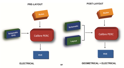
The first requirement is a SPICE netlist, which can be either a schematic netlist or a netlist extracted from the layout. In the latter case, the LVS-like runset used for extraction must ensure that all ESD protection devices are extracted (Note: parasitics are not extracted, just intentional devices). While the netlist must contain the proper text names for device pins (so that power and ground domains can be established), in general, texting in the netlist is not used extensively for verification (see Figure 2).

Figure 2: Hierarchical verification flow
The second input is an ESD rule deck. It specifies the ESD design rules to be checked, and the list of power and ground domain names. Power and ground names are not generated automatically; they must be specified in the rule deck per the design specification. This rule deck is essential for making the verification method generic. For ease of discussion, however, we will describe the method in the context of the ESD design rule formulated above.
Conceptually, the hierarchical algorithm runs in two steps:
1) initialization, and 2) rule-checking. In the initialization step, the algorithm gathers ESD-related topology information from each cell and propagates it throughout the design. In the second step, the algorithm checks ESD design rules independently, cell by cell, as each cell now has access to the entire ESD protection scheme propagated from all other cells.
ESD Rule-Checking
Once net connectivity is defined, we can check the ESD design rule cell by cell. Since a net’s path through devices is, in general, instance-dependent, we cannot just check each cell once. Instead, we find a list of representative instances with unique net connectivity for each cell. Depending on the amount of regularity in the design, the list of instance representatives can be orders of magnitude smaller than the list of all instances for a cell. This greatly improves the speed of the tool compared to checking a flat netlist and is done while preserving any instance specific configurations.
Rule Deck Coding Considerations
Given the diversity in ESD rules, it is important to develop a robust rule deck that will not miss real violations. Within the framework of our method, there are two basic approaches: one is to code a new rule for each variation, and the other is to code a single general purpose rule that covers all variations. The tradeoff is speed vs. rule complexity. The first approach is simpler but slower, as each net will be checked multiple times (once for each rule). The second approach is faster but obviously more complex.
The rules should include checking of properties of the ESD protection devices, such as ESD components widths. Also, the rules should handle different protection types. For example, the ESD protection circuit in Figure 1 could be a dynamic or static clamp or diodes.
Similarly, the drivers and receivers in real circuits are not necessarily simple inverters. They can be NANDs, NORs, etc. However, this does not need special attention from the rule-writing point of view. The tool automatically handles different types of logic gates.
Moreover, the tool can recognize multiple drivers/receivers on an interface net—for instance, a driver with a fan-out to three inverters (in the same domain or in different domains). The rules should take advantage of this ability and report all drivers/receivers associated with a violation.
At the global level, a robust rule deck should also include other ESD checks. For example, the parameters used in the domain crossing interface check can be dependent on properties of the supply protections. As an example, in the case shown in Figure 1 where the driver and receiver have separate VDDs and VSSs, we are able to make a determination of the checks to be performed and determine the need for the specific protection circuit specified (in this case, anti-parallel diodes).
Results
ESD rule decks have been written using this technique and have been verified in production design flows for both large blocks and complete chips. We will review the results in terms of functionality (How well did it identify real problems?) and reporting (How easy is it for users to manage and correct errors?).
Functionality
In practice, designs with multiple power and ground domains often involve hundreds or thousands of crossings that need to be verified. In addition to determining what signals require ESD clamps for protection, the crossing audit is also needed to determine which ground domains need interface protections.
In one example, for noise isolation purposes, a PLL was designed with separate ground domains for the core and 1.8V circuits. Traditionally, crossings between domains were checked manually to see if ESD clamps were present. However, crossings can be very difficult to find, since the connections may need to be traced through multiple schematics and there can be hundreds, if not thousands, of crossings. Using the PLL example, the hierarchical ESD audit identified all 133 crossings in just a few seconds. The crossing audit also successfully caught missed instances of clamps in the preliminary design.
Reporting
The output from the rule deck lists all the crossing nets and is organized by hierarchy (Figure 3). For each net, the MOSFETs on both sides of the interface, together with the associated grounds, are shown. This output can be customized as desired, and Calibre PERC provides a results viewing environment (Calibre RVE) to highlight devices in the schematic and/or layout when they are selected in the report. All 133 results are displayed in the graphical tree view shown in Figure 3. Analysis of these results will identify the specific details for each failure.

Figure 3: Results for an entire design showing an ESD protection error on net 2767, involving one receiver and three drivers
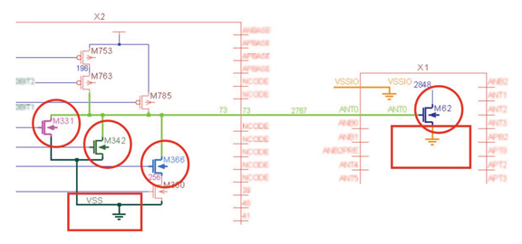
The schematic representation in the results viewer can provide a different perspective of an error (Figure 4) This often provides a holistic view of the connectivity, enabling much easier debugging than the original schematic. Of course, as these results are displayed in Calibre RVE, highlighting back to the original schematic is also supported.

Figure 4: Schematic image from results viewing, identifying all the circuitry elements affected by the error: Net 2767, Receiver: X1/M62, Drivers: X2/M331, X2/M341, X2/M366, Ground nets VSS and VSSIO
Because you can specify nets, devices, pins, etc., and create “groupings” for testing conditions, the tool can use these conditions to determine how to evaluate a design.
Conclusion
In this paper, we presented a well-established, topologically-driven hierarchical verification methodology that has been developed to automate ESD rule-checking. It can handle large ICs and check ESD protection rules on the original design without netlist reduction. The hierarchical algorithm uses a novel topology-aware concept, allowing for verification of chip-level ESD design rules. The presented method has been extensively verified and is being used in production to significantly improve ESD quality.
Until now, there has been a clear gap in EDA solutions to address the demands of circuit and electrical verification. The ability to use both netlist and layout (GDS) information simultaneously to perform electrical checks enables designers to address both reliability concerns arising from crossing multiple power domains and catastrophic failures from ESD that can have large effects on yield and reliability. In addition, this method can employ topological constraints to verify that the correct structures are in place wherever circuit design rules require them. An automated solution that verifies circuits at both the schematic and layout phase can reduce cost and time to market, while improving yield and device reliability. ![]()
References
- M. Ker, C. Wu, H. Chang, and T. Wu, “Whole Chip ESD Protection Scheme for CMOS Mixed-mode IC’s in Deep-submicron CMOS Technology”, Proceedings of the IEEE Custom Integrated Circuits Conference, 1997, pp. 31-34.
- H. Abrishami, et al., “NBTI-aware Flip-flop Characterizationand Design”, GLSVLSI’08,May 4–6, 2008.
- B.C. Paul, K. Kang, H. Kuflouglu, M. A. Alam, and K. Roy, “Impact of NBTI on the Temporal Performance Degradation of Digital Circuits”, Electron Device Letter, Vol. 26, No. 8, Aug. 2005, pp. 560-562.
- Hong Luo, et al., “Modeling of PMOS NBTI Effect Considering Temperature Variation”, 8th International Symposium on Quality Electronic Design (ISQED’07), 2007.
- Jin Qin, et al., “SRAM Stability Analysis Considering Gate Oxide SBD, NBTI and HCI”, IIRW Final Report, 2007.
- J. Lee, K. Kim and S. Kang, “VeriCDF: A New Verification Methodology for Charged Device Failures”, Proceedings of the 39th Design Automation Conference, 2002, pp. 874-879.
- H. Qian, J.N. Kozhaya, S.R. Nassif, and S.S. Sapatnekar, “A Chip-level Electrostatic Discharge Simulation Strategy”, Proceedings of the IEEE/ACM International Conference Computer Aided Design, 2004, pp. 315-318.
- M. Baird and R. Ida, “Verify ESD: A Tool for Efficient Circuitlevel ESD Simulations of Mixed-signal ICs”, Proceedings of the EOS/ESD Symposium, 2000, pp. 465-469.
- J. Willemen and L. Cerati, “ESD Design in High Voltage Technologies”, Private Communication, May 14, 2012.
- Shih-Hung Chen, Ming-Dou Ker, and Hsiang-Pin Hung, “Active ESD Protection Design for Interface Circuits Between Separated Power Domains Against Cross-power-domain ESD Stresses”, IEEE Transactions On Device And Materials Reliability, Vol. 8, No. 3, September 2008, pp 549-560.
- J. Lee and E. Rosenbaum, “Voltage Clamping Requirements for ESD Protection of Input in 90nm CMOS Technology”, Proceedings of the 30th EOS/ESD Symposium, 2008, pp. 50-58.
- T. Smedes, N. Trivedi, J. Fleurimont, A.J. Huitsing, P.C. de Jong, W. Scheucher, and J. van Zwol, “A DRC-based Check Tool for ESD Layout Verification”, Proceedings of the EOS/ESD Symposium, 2009.
- EDA Tool Working Group. ESD Electronic Design Automation Checks (ESD TR18.0-01-11), New York: Electrostatic Discharge Association, 2011. www.esda.org/Documents.html
- M. Khazhinsky, “ESD Electronic Design Automation Checks”, In Compliance Magazine, August 2012.
At the time of writing, the ESDA EDA Working Group consisted of the following members: Michael Khazhinsky (Silicon Labs), Fabrice Blanc (ARM),
Gianluca Boselli (Texas Instruments), Shuqing (Victor) Cao (Global Foundries), Norman Chang (Ansys), Dan Clement (On Semiconductor), Rosario Consiglio (Impulse Semiconductor), Maxim Ershov (Silicon Frontline), Melanie Etherton (Freescale Semiconductor), Eleonora Gevinti (ST), Harald Gossner (Intel), Matthew Hogan (Mentor Graphics), Larry Horwitz (Synopsys), Kelvin Hsueh (ESD Consultant), Mujahid Muhammad (IBM), Louis Thiam (Cadence), Nitesh Trivedi (Infineon), Vesselin Vassilev (Novorell).
Founded in 1982, the ESD Association is a professional voluntary association dedicated to advancing the theory and practice of electrostatic discharge (ESD) avoidance. From fewer than 100 members, the Association has grown to more than 2,000 members throughout the world. From an initial emphasis on the effects of ESD on electronic components, the Association has broadened its horizons to include areas such as textiles, plastics, web processing, cleanrooms and graphic arts. To meet the needs of a continually changing environment, the Association is chartered to expand ESD awareness through standards development, educational programs, local chapters, publications, tutorials, certification and symposia.
This article has not been reviewed by the ICM Editorial Advisory Board.
 |
Matthew Hogan is a Calibre Marketing Engineer for Mentor Graphics, with over 15 years of design and field experience. He is an active member of the ESD Association involved with the EDA working group and Symposium technical program committee. Matthew is a Senior member of IEEE and member of ACM. He holds a Bachelor of Engineering from the Royal Melbourne Institute of Technology and an MBA from Marylhurst University. He is actively working with customers who have an interest in Calibre PERC and 3D-IC. Matthew Hogan can be reached at matthew_hogan@mentor.com. |
