
The obvious solution to a problem isn’t always the best.
For example, will making a grounding rod longer or a grounding system bigger always reduce the risk of lightning damage? Reality may be different from expectations.
One way to set expectations is to study the effect of a ground rod on the waveshape of a surge, which can tell us a lot about how the ground rod is behaving. Standards have advice on this. For example, based on a reading of the IEC 61312-1 [1] standard, we might assume that the waveshapes of the current flowing in the grounding system and that flowing in the electrical circuit are the same – implying that the grounding system is simply a resistance. But is that really the case?
The obvious solution to a problem isn’t always the best.
Lightning Measurements at Structures
For another view, consider the work of Rakov, Uman and their associates at the Camp Blanding triggered lightning facility in Florida. They have a facility with a launch tower [for rocket-induced lightning] and an instrumented building. They have shown [2] that the waveshapes of the currents in the grounding system and those entering the building electrical circuits are considerably different [in their case for a subsequent surge]; and they attribute the difference to the performance of the ground rods in the two cases.
That observation suggests that we need to look more closely at the effects of ground rods on an incident lightning waveform. Maybe ground rods can act differently than the IEC expects. From the recorded waveforms of the currents at the launch tower and at the ground rods, Rakov et al found that the surge currents in the ground rods have a much faster rise time and a much shorter duration than those of the incident surge. (As explained in the January 2005 IEEE Transactions on Power Delivery [3], this lightning is mostly subsequent strokes.)
So what’s going on? The short explanation is that the ground rods used in the study by Rakov et al [2] are acting like lossy capacitors – probably not what most of us would expect. This observation also suggests that ground rods may have other behavior that we don’t expect, so let’s look at what is known about them.
Ground Rods (or Horizontal Ground Wires)
The analysis of the behavior of ground rods also applies to horizontal ground wires, so in this article, the term “ground rods” will include horizontal ground wires. Generally, ground rods have been assumed to behave like resistors. The unexpected behavior occurs because ground rods also have reactive elements. The effect of these reactive elements on the wave shape of a surge will be greatest on high frequency components of the surge. The high frequency components of the surge primarily affect the surge rise-time, so the reactive elements of a ground rod may change the rise-time of the surge. The fall-time is generally less affected, depending on the type of surge and the resistance of the ground rod.
To assess their impact on lightening, quite a bit of work has been done recently on the high-frequency behavior of ground rods [4]. The results can be divided into two categories: short ground rods which look capacitive, and long ground rods which look inductive [5].
Short Ground Rods
Short ground rods are most likely to be found at residences. A number of groups ([6][7][8]) have estimated the capacitance of short ground rods, with estimates running around 3.3 nF for a 2 m long ground rod.
The ground rod capacity is in parallel with the resistance of the ground, so the effect of the capacity depends in the resistivity of the soil. As a review, the resistance of a ground rod as a function of soil resistivity and length can be calculated from Dwight’s 1936 calculation [9]:
![]() (1)
(1)
where ρ is the resistivity of the ground, l is the length of the ground rod, and a is its diameter. The values of l/a typically run from about 280 for 2 m ground rods to 2520 for 32 m ground rods.
Using a linear approximation for l/a, (1) can be written:
![]() (2)
(2)
Now consider a subsequent surge, since that has the fastest rise and fall times, and is most affected by the reactance of the ground rod. A typical short ground rod is 2 m long. This ground rod in low resistivity (50 ohm-m) and high resistivity (3000 ohm-m) soil would have a resistance of about 25 ohms and 1400 ohms, respectively. Using these resistances and a capacitance of 3.3 nF, the response to a subsequent surge as characterized in [3] is shown in Figure 1. This figure shows that a ground rod in low resistivity soil is characterized by a modest slowing of the rise time of the surge. The curve for the 3000 ohm-m soil has a much greater slowing of the rise time and a higher amplitude than that of the 50 ohm-m soil because the resistance of the ground rod is higher, leading to a higher voltage for the same reference current.

Figure 1: The voltage developed across a short (2 m) ground rod for a typical subsequent surge current
Long Ground Rods
Long ground rods may be driven at commercial structures to lower the surge resistance to ground. Long horizontal ground wires and grounding grids also fall into this category. These have been characterized using transmission line analyses; e.g. Verma [10] for ground rods and wires, and Gupta[11] and Grecv [12] for grounding grids. As pointed out in Grecv, circuit-based models tend to overestimate voltages compared to transmission line models. But in that sense, circuit-based models are conservative.
Transmission line analysis is necessary for very long grounding systems (e.g. over 30 m) and any system in which reflections from discontinuities is important. For ground rods that are not too long (e.g. less than 30 m), it is simpler to calculate the inductance of the ground rod and then calculate the response of a series R-L circuit. The inductance of the ground rod is given in Verma as:
![]() (3)
(3)
where l and a are as given in (1). Using the same approximation as was used to obtain (2), (3) can be written as:
![]() (4)
(4)
From (4), a 10 m ground rod has an inductance of 15 µH, and a 30 m ground rod has an inductance of 51 µH.
Considering inductive effects alone, Figure 2 shows that in low resistivity soil, a short ground rod has a relatively small inductive effect on a fast-rising subsequent surge. (The initial shape of the curve in this case may be an artifact of the calculation.) A longer ground rod (30 m) has a large inductive effect on a subsequent surge. The 30 m rod has about 15x less resistance than the 2 m rod, hence a lower ultimate voltage drop.
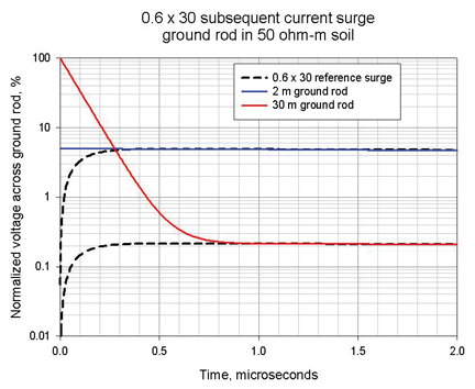
Figure 2: The voltage developed across various ground rods by a subsequent surge in low-resistivity soil
Figure 3 shows that, in high resistivity soil, a short (2 m) ground rod has basically no inductive effect on a subsequent surge because its resistance dominates its inductance. A Longer (30 m) ground rod has a significant effect, but much less than it has in low resistivity soil.

Figure 3: The voltage developed across various ground rods by a subsequent surge in high-resistivity soil
The results illustrated above are dependent on the assumptions made in the calculations. Nevertheless, some general conclusions can be drawn. Short ground rods are most simply modeled by a parallel RC circuit, where the resistance is determined by the resistivity of the soil and the capacitance can be estimated at about 3 nF. Long ground rods are most simply modeled by a series RL circuit, where again the resistance is determined by the resistivity of the soil. Table 1 summarizes general conclusions about the dominant effects of ground rod length and soil resistivity.
| Rod type and soil resistivity | Reactive effect | Relative resistance | Effect on rise time | Leading edge spike | Voltage beyond the spike |
| Short, low ρ | Capacitive | Low | Least | None | Low |
| Short, high ρ | Capacitive | High |
Most | None | High |
| Long, low ρ |
Inductive |
Low | Most | Highest | Low |
| Long, low ρ | Inductive | High | Least | Moderate | High |
Table 1
The Practical Effect of Ground Rods
We have seen how, from a surge standpoint, ground rods can be either capacitive or inductive in nature, depending on their length and the resistivity of the soil. The practical effect of a ground rod depends on the frequency content of the incident surge. A double exponential of the form
exp(−at) − exp(−bt) can be represented in the frequency domain as
![]() (5)
(5)
where s = jω
For a typical first surge, a = 2.52×10³ and b = 1.26×10⁶; and for the subsequent surge, a = 2.38×10⁴ and b = 1.11×10⁷ (cf. [3] [13]) So from (5) the normalized frequency spectrums of these surges look like Figure 4.

Figure 4: Normalized spectrum of a 4.5×77 and a 0.6×30 surge
What is clear from Figure 4 is that the high amplitude part of both the 4.5×77 and the 0.6×30 surges is concentrated at low frequencies. At low frequencies, a ground rod is essentially resistive. Since resistance decreases as the length of a ground rod increases, a long ground rod helps to reduce the specific energy (Amp2sec) of the surge by diverting the relatively high-amplitude, low-frequency components to ground. But a long ground rod looks inductive at higher frequencies, and this effect can lead to potentially damaging voltage spikes. So at what length does the inductive effect become important?
The Concept of Impulse Coefficient and Effective Length
Grecv [4] has defined the effective length of a ground rod as
![]() (6)
(6)
where
![]() (7)
(7)
![]() (8)
(8)
ρ = soil resistivity in ohm-m and T1 is the zero-to-peak rise time of the lightning current pulse. We can use (7) and (8) to make a plot of leff vs. ρT1, as shown in Figure 5.

Figure 5: Variation in the effective length of a ground rod with soil resistivity and the zero-to-peak time of the surge
If the length l of the ground rod is less than leff, the ground rod is primarily resistive, with a possible capacitive effect. If the length l of the ground rod is greater than leff, the ground rod will have inductive effects. As they are potentially damaging, how big are the reactive effects for a ground rod of a given length? Grecv [4] has proposed the relation
![]() (9)
(9)
where A = Z/R is the impulse coefficient (defined as the ratio of peak voltage to the peak voltage across a purely resistive ground rod or wire) and R = ground rod resistance.
For A > 1, the ground rod has a series inductance in addition to its resistance. In this case, the peak voltage will be A times bigger than it would have been if the ground rod were purely resistive.
For A < 1, the ground rod has a parallel capacitance in addition to its resistance. In this case, the peak voltage will be A times lower than it would have been if the ground rod were purely resistive.
From (9) the effect of the ground rod reactance can be calculated. As an illustration, take the four cases of ρT1, = 100, 300, 1000 and 10,000 and use (9) to plot A vs. length of rod. The result is shown in Figure 6.

Figure 6: Impulse coefficient versus length of ground rod (or wire)
Conclusion
Back in the beginning we said that the work of Rakov et al [2] was at odds with the IEC 61312-1 statement that the wave shapes of the current flowing in the grounding system and that flowing in the electrical circuit are the same. Now we can see that in order for the IEC 61312-1 statement about wave shapes to be valid, it must also be assumed that ground rods are purely resistive. Here we have shown that ground rods are resistive only under some conditions and that, in general, they also have a reactive component which can significantly affect the wave shape of the surge voltage, especially for subsequent surges.
The point is that when we think of grounding systems, we tend to think only of resistance and how resistance can be reduced. But the things we do to lower resistance may increase inductance, which could actually make matters worse, especially for fast-rising secondary surges. This is something to bear in mind when designing protection.
![]()
References
- IEC Standard 61312-1, Protection Against Lightning Electromagnetic Impulse- Part 1: General Principles.
- V. A. Rakov et al, “Direct Lightning Strikes to the Lightning Protective System of a Residential Building: Triggered-lightning Experiments,” IEEE Transactions
on Power Delivery vol. 17, no. 2 (April 2002). - “Parameters of Lightning Strokes: A Review,” IEEE Transactions on Power Delivery vol. 20, no. 1 (January 2005).
- L. Grecv, “Impulse Efficiency of Ground Rods,” IEEE Transactions on Power Delivery vol. 24, no. 1 (January 2009), 441-451.
- A. Rousseau, “Lightning Earthing System: A Practical Guide,” Proceedings of the International Lightning Protection Association, 1st Symposium, (Valencia, Spain, 2011).
- B. H. Lee, J. H. Joe, and J. H. Choi, “Simulations of Frequency-dependent Impedance of Ground Rods Considering Multi-layered Soil Structures,” Journal of Electrical Engineering and Technology vol. 4, no. 4 (2009), 531-7.
- R. S. Alipio, M. A. O. Schroeder, M. M. Afonso, and T. A. S. Oliviera, “The Influence of Soil Parameters Dependence with Frequency on Impulse Grounding Behavior,” Proceedings of the Xth International Symposium on Lightning Protection (Cruitiba, Brazil, 2009), 369-373.
- A. Rousseau, M. Guthrie, and V. Rakov, “High Frequency Earthing Impedance Measurements at
Camp Blanding, Florida,” 39th International Conference on Lightning Protection – ICLP 2010 (Cagliari, Italy, 2010), 1303.1-1303.9. - H. B. Dwight, “Calculation of Resistances to Ground,” Transactions of the American Institute of Electrical Engineers vol. 55 (1936), 1319-1328.
- R. Verma and D. Mukhedkar, “Impulse Impedance of Buried Ground Wire,” IEEE Transactions of Power Apparatus and Systems vol. PAS-99, no. 5 (1980), 2003-2007.
- B.R. Gupta and B. Thapar, “Impulse Impedance of Grounding Grids,” IEEE Transactions on Power Apparatus and Systems vol. PAS-99, no. 5 (1980), 2357-2362.
- L. Grecv and V. Arnautovski-Toseva, “Grounding Systems Modeling for High Frequencies and Transients: Some Fundamental Considerations,” IEEE Bologna Power Technical Conference, June 23-26 (Bologna, Italy, 2003).
- A. Martin, “Lightning-induced GPR: Why It’s a Problem, Characteristics and Simulation,” In Compliance Magazine (June 2012).
- “Bibliography of Research on Parameters of Lightning Strokes,” See www.ewh.ieee.org/soc/pes/lpdl/TF_minutes/parm_biblio.html.