Associate Professor Neils Jonassen authored a bi-monthly static column that appeared in Compliance Engineering Magazine. The series explored charging, ionization, explosions, and other ESD related topics. The ESD Association, working with In Compliance Magazine is re-publishing this series as the articles offer timeless insight into the field of electrostatics.
Professor Jonassen was a member of the ESD Association from 1983-2006. He received the ESD Association Outstanding Contribution Award in 1989 and authored technical papers, books and technical reports. He is remembered for his contributions to the understanding of Electrostatic control, and in his memory we reprise “Mr. Static”.
~ The ESD Association
Reprinted with permission from: Compliance Engineering Magazine, Mr. Static Column Copyright © UBM Cannon
Screening noncontacting meters will often reduce the field distortion caused by the presence of meters.
Anyone who has worked with static or dynamic electricity is familiar with the concept of voltage. After all, Ohm’s law states that V = R ∙ I, voltage (difference) equals resistance times current. But this well-known relationship does not say anything about voltage; rather, it defines resistance, and it cannot be applied to ESD problems because there is no current. Then there is the definition of the voltage difference between points A and B as the work done per unit charge when a charge is brought from A to B. But here there is a metrological problem because there is no way to measure the work that is done on a charge. So, we have to go back to the basics and realize that voltage is not a fundamental quantity, but rather a property of an electric field.

Figure 1 shows a section of a homogeneous field with field strength E, where the voltage difference between points A and B is defined by
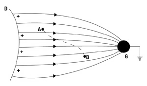
However, in most cases, fields are not homogeneous. Figure 2 shows the field from a positively charged insulator with a grounded conductor placed in front of the insulator. In this case, the voltage difference between A and B is defined by

Equations 1 and 2 only define voltage differences. The voltage of a point P in a field is defined as the integral of the field from P to infinity or to any grounded object, that is,

Voltage of a Conductor
Figure 3 shows an insulated conductor A with a charge q.

The charge will automatically distribute itself on the surface of the conductor in such a way that (a) the field in the interior of the conductor is zero, (b) the field is perpendicular to the surface, and (c) the integral of the field strength from any point P in or on the conductor to a ground point G is constant:

V is the voltage or potential of the conductor. The voltage V and the charge q are proportional, and this is usually written as

C is the capacitance of the insulated conductor and is determined by the size and shape of the conductor and its placement relative to other conductors and ground.
The charged system stores an electrostatic energy given by

which can be dissipated in a single discharge or current pulse.
Measurement of Conductor Voltage
Direct-Contact Voltmeters
The voltage of an insulated conductor may be measured directly by connecting the conductor to an electrometer or static voltmeter (see Figure 4). The voltmeter measures the common voltage of the conductor and the voltmeter. If the capacitance C of the conductor is much larger than the capacitance Ci of the voltmeter, the voltage read on the voltmeter is, with good approximation, equal to the voltage of the conductor without the meter being attached.
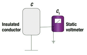
However, the measuring range of most static voltmeters is in the order of tens or, at best, hundreds of volts. On the other hand, static voltages will often be in the kilovolt range.
This problem can be circumvented by the use of a capacitive voltage divider. In Figure 5, a capacitor with capacitance Cy is inserted in the connection between the conductor and the static voltmeter.

If the voltage read on the voltmeter is Vi, then the voltage V of the conductor is given by

As an example, let us assume that the maximum voltage to be read on the meter is Vi, max = 10 V, Ci = 10 nF = 10–8 F, and Cy = 10 pF = 10–11 F, then Equation 7 will give a maximum voltage of

The necessary high capacitance in this application of the meter is usually obtained by running the meter in the charge-measuring mode. It appears that using a capacitive voltage divider expanded the measuring range of the voltmeter by a factor of 1000.
Noncontacting Measurements
Electrostatic noncontacting measurements are always based on the effects of the fields of charges, whether they are located on conductors or insulators. There are basically two types of instruments: field meters, which measure the charge induced on a probe and convert it to the field strength in front of the probe, and noncontacting voltmeters, which raise the voltage of the probe until the field in front of the probe is zero. The noncontacting voltmeter then takes this voltage as
the voltage of the object that it is pointing toward.
Noncontacting voltmeters may have greater sensitivity (but not necessarily greater accuracy) than do field meters. However, both types of instruments may distort the original field considerably unless the meters are suitable screened.
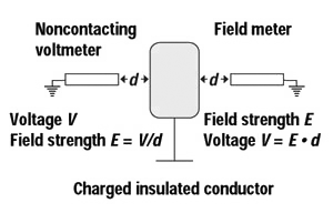
Figure 6 shows a charged insulated conductor. In the figure, the noncontacting voltmeter reads the voltage V of the conductor and estimates the mean field strength E = V/d between the conductor and the meter, whereas the field meter reads the field strength E in front of the meter and estimates the voltage V = E ∙ d of the conductor. However, it should be emphasized that the quantities read and calculated refer to the conditions that exist when the instruments are in place.
Conductor at Fixed Voltage
The experiment shown in Figure 7 was conducted to investigate the influence of the meters on the field from and the voltage of the charged conductor. A 35 ∙ 35-cm metal plate was connected to a voltage supply kept at a constant voltage of 3 kV. A field meter was placed perpendicular to the plate, pointing at the center of the plate, and the field strength E was measured as a function of the distance d between the plate and the field meter. For each distance d, the product E ∙ d was calculated.
The results of the measurements are shown in Figure 8. It appears that the field strength E decreased with increasing distance d, as expected. However, if the voltage V of the plate is calculated from Equation 1 as V = E ∙ d, the result would be a very poor approximation of the true value (3 kV) of the plate voltage.
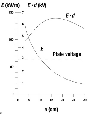
The reason for this is that Equation 1 assumes the field to be homogeneous, as shown in Figure 1. But the setup in Figure 7 resembles much more closely the situation in Figure 2 because the housing of the field meter (or for that matter, the housing of a noncontacting voltmeter) is essentially at ground potential. The field strength read on the field meter (or compensated for in a noncontacting voltmeter) is therefore higher than the mean field strength between the meter and the target, and the E ∙ d approximation of the voltage will therefore be too high. Figure 8 shows that in the range of distances from 4 to 30 cm, the estimated voltage E ∙ d varies between 4.5 and 6.2 kV, rather than the true value of 3 kV.
The problem of the instruments distorting the field can be corrected partly by surrounding the meter with a grounded screen placed parallel to the face of the target, as shown in Figure 9. The experimental setup had a 25 ∙ 25-cm screen and a 35 ∙ 35-cm metal plate as the target.
Figure 10 shows the field strength E and the apparent voltage E ∙ d as a function of the distance d. The results demonstrate that, with the screen attached, the voltage V of the metal plate is adequately determined by the product E ∙ d out to a distance of approximately 15 cm between the plate and the field meter. In this range, the field is homogeneous and inversely proportional to the distance to the field meter, that is, the E-field curve is a hyperbola. At larger distances, the field again becomes inhomogeneous, and at this range, the field meter underestimates the voltage.

The distance to which the voltage can be determined with reasonable accuracy also depends on the target size. If the measurements in Figure 10 were repeated with a 15 ∙ 15-cm plate, the readings would yield reliable results only out to a distance of approximately 6–7 cm.
Conductor with Constant Charge
In the previously discussed cases, the target conductor was locked to a voltage supply. The voltage of the conductor would therefore be kept constant, independent of field meter placement. The charge, on the other hand, might vary with the intercapacitance of the conductor and the field meter, that is, with the distance d.
The previous cases do not represent the ordinary, everyday situation in which a conductor has been charged and the voltage is measured by pointing a meter at the conductor. In this more common case, the charge stays constant while the voltage may change because of the coupling with the meter capacitance. Figure 11 shows an experimental setup for investigating this situation. In the experiment, a 35 ∙ 35-cm metal plate was charged to an initial voltage of 3 kV (in the absence of the field meter), and then the connection to the voltage supply was broken. Next, the field meter was placed at various distances d from the metal plate, and the field strength E was measured.
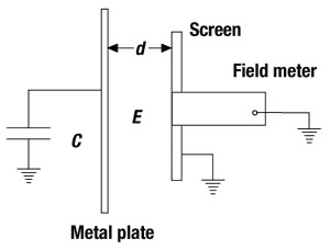
Figure 12 shows the product E ∙ d (the apparent voltage) as a function of d for plate capacitances C ≅ 20 pF (the plate alone) and C ≅ 220 pF (the plate and an additional external capacitor). The greater plate capacitance of 220 pF provided a curve that is very similar to the one plotted in Figure 10, where the metal plate was locked at 3 kV. This means that the presence of the field meter does not significantly change the total capacitance and, hence, the plate voltage for a given distance. The lesser plate capacitance of 20 pF resulted in a calculated voltage that is lower at all distances than that found with the plate of greater capacitance. This is due to the added value of the meter capacitance. At the very short measuring distance, the presence of the meter increases the original value of the capacitance from 20 to about 45 pF, resulting in the voltage dropping from 3 to about 1.3 kV.
The measurements reported in Figure 12 were repeated with an unshielded field meter. The general trend was the same as demonstrated in Figure 8. At all distances (and with both capacitances tested), the unshielded field meters overestimated the true values of the plate voltage by up to 100%.

Static Locators
Probably the most common way to do a fast static survey is to point a handheld meter at the suspicious item and pronounce a voltage. Often, this is the only measurement done. And very often, this is not enough.
These handheld meters are known as, and often even called, static locators. And that is exactly what they are— instruments to locate a static electric field. As long as that is the only thing they are being used for, everything is fine. But often, their use is being extrapolated into the absurd.
Figure 7 is an illustration of the typical use of a field meter as a static locator. The meter ranges may be in volts, but the meter is not a voltmeter. It does not react to a voltage, but rather to an electric field. Often, it is a regular field meter, for instance, a field mill, or it may essentially just contain an operational amplifier that reacts to the charge induced on a sensor plate at the front of the meter housing.
The meter also has a stipulated measuring distance. In the case shown, it is d. This means that the meter was calibrated by placing it at a distance d from, and parallel to, a metal plate, which was then raised to a range of voltages, and a corresponding scale was drawn.
So the question is this, after the calibration, what can the meter be used for? The answer is very simple: The meter can be used to measure the electric field at a distance d from a metal plate with the same dimensions and the same capacitance as the one used for factory calibration. For conductors, the value obtained is approximately equivalent to surface voltage. At any other distance or when measuring insulators, the measurement is not calibrated and the instrument has merely located an electric field.
The problem is that manufacturers seem very reluctant to mention this, or to just describe what the calibration conditions were and what happens if the instrument is used under other, and maybe even more-everyday, conditions. It is very rare, if it ever happens at all, for the dimensions of the calibration plate, not to mention its capacitance, to be given in the manual. Nor is there any warning that if the meter were to be pointed toward an insulator, the reading in volts would never refer to the insulator as a whole. As was mentioned in Part I of this article, an insulator does not have a voltage. If the user is lucky, a kind of surface voltage may be found.1
It is something of a puzzle why static locators are always calibrated in volts. After all, they are just ordinary field meters pretending to be voltmeters, without really being so. All they can do is measure the voltage of a certain metal plate at a certain distance. If these meters were calibrated in units of field strength, that is, V ∙ m–1, they could be used much better to evaluate the static conditions of insulators as well as conductors.
But could the explanation simply be that most people understand voltage better than they do field strength? No, that does not seem possible. Just look at Equations 1, 2, and 3 of this article. A voltage is always defined by a field strength (and a distance), so if someone does not understand one, that person would not understand the other.
Conclusion
This article has analyzed the problems connected with measuring the voltage of a charged insulated conductor. The emphasis was placed on noncontacting measurements, that is, measurements based on the effect of the field from the charge. It has been demonstrated that the instruments used will often distort the fields and hence change the properties to be measured. It was also shown that, by screening the meters, it is often possible to reduce the field distortions considerably. ![]()
Reference
- Niels Jonassen, “Surface Voltage and Field Strength: Part I, Insulators” in Mr. Static, Compliance Engineering 18, no. 7 (2001): 26–33 and In Compliance Magazine, August 2012.
 |
Niels Jonassen, MSc, DSc worked for 40 years at the Technical University of Denmark, where he conducted classes in electromagnetism, static and atmospheric electricity, airborne radioactivity, and indoor climate. After retiring, he divided his time among the laboratory, his home, and Thailand, writing on static electricity topics and pursuing cooking classes. Mr. Jonassen passed away in 2006. |
