If your EMI filter is failing in high frequencies, check the frequency response of the components: parasitics limit the filtering effectiveness.
In any EMI/EMC problem we have three elements: a culprit, a victim, and a coupling mechanism; and a common technique to solve those problems is reducing the coupling mechanism using an EMI filter.
EMI filters are usually low pass passive topologies using inductors and capacitors.
Consider for example an ideal design for a second order filter designed for 50ohm-50ohm terminal impedances as in Figure 1. Be careful! Remember in the real application terminal impedances are usually unknown.

From the insertion loss (IL) response (blue trace), we can predict more than 60dB at frequencies higher than 400kHz. Note we need a 130uH inductor and a 2uF capacitor, typical values for a conducted emissions problem.
But consider the filter is not effective in high frequencies. Why at high frequencies insertion loss are not as high as expected from the theoretical calculations?.
If the filter is analyzed in the real situation, a different response is obtained as you can see in red in Figure 2.

At frequencies lower than 200kHz, the ideal response is equal to the real response. At frequencies higher than 100MHz the real filter has no effect (IL=0dB). For the frequency range between 400kHz and 100MHz insertion losses are really different from the ideal design.
If we are using this filter for conducted emissions from 150kHz to 30MHz the results will be really bad.
Situation is even worse if you cannot measure the real response and you continue adding components to the filter trying to obtain the desired IL value.
One of the most useful instruments for your laboratory is an impedance analyzer. I have a really good Agilent 4294A with 40Hz to 110MHz frequency range.
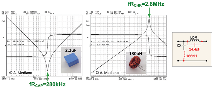
In Figure 3, you can see the frequency response for the 2uF and 130uH I used in my prototype measured by the 4294A.

Note the capacitor has a SRF (self-resonant frequency) of 280kHz. At frequencies below 280kHz the component is capacitive. For frequencies higher than 280kHz the component is inductive (measurement give us a 166nH value for that parasitic inductance).
The inductor has SRF equal to 2.8MHz so the component is inductive (130uH) below that frequency but the inter-winding parasitic capacitance (24.4pF) is dominant at higher frequencies.
As you can see in Figure 3 the equivalent circuit for our filter switch from a low pass topology at low frequencies to a high pass topology at high frequencies: we have a notch filter because the parasitics in the components!.
The minimum peaks in the response of the filter (red trace in Figure 2) match the resonant frequencies of the components because at 280kHz the capacitor is near a short circuit and at 2.8MHz the inductor is a high impedance with the result of good insertion losses at those frequencies.
Note that, increasing the nominal value of the components to obtain a better filtering effect is only effective at low frequencies because with bigger components (usually with higher parasitics), the self-resonant frequencies are reduced and behavior in high frequencies is destroyed.
My final advice: be sure you know the limits for your components, measure your components!
 Arturo Mediano received his M.Sc. (1990) and his Ph. D. (1997) in Electrical Engineering from University of Zaragoza (Spain), where he has held a teaching professorship in EMI/EMC/RF/SI from 1992. From 1990, he has been involved in R&D projects in EMI/EMC/SI/RF fields for communications, industry and scientific/medical applications with a solid experience in training, consultancy and troubleshooting for companies in Spain, USA, Switzerland, France, UK, Italy, Belgium, Germany, Canada and The Netherlands. He is the founder of The HF-Magic Lab®, a specialized laboratory for design, diagnostic, troubleshooting, and training in the EMI/EMC/SI and RF fields at I3A (University of Zaragoza), and from 2011, he is instructor for Besser Associates (CA, USA) offering public and on site courses in EMI/EMC/SI/RF subjects through the USA, especially in Silicon Valley/San Francisco Bay Area. He is Senior Member of the IEEE, active member from 1999 (Chair 2013-2016) of the MTT-17 (HF/VHF/UHF) Technical Committee of the Microwave Theory and Techniques Society and member of the Electromagnetic Compatibility Society. Arturo can be reached at a.mediano@ieee.org.

