 The ICS 105 IC scanner from Langer EMV can be used together with the ICR near-field microprobes to measure high-frequency near fields above integrated circuits (ICS 105 GND set) and small modules (ICS 105 UH set). The analysis of an IC’s near fields provides a better understanding of what happens inside the IC at high frequencies. The measurements help analyze an IC’s emission problems and pinpoint its areas which are responsible for the emissions.
The ICRHH 150-27 near-field microprobe has a horizontal measurement coil to measure magnetic fields. It enables a resolution of 50 µm in the measurement range between 1.5 GHz and 6 GHz.Apart from the ICR near-field microprobes from Langer EMV-Technik GmbH, hand-held probes or field sources can be fitted to the ICS 105 using the SH 01 probe holder.
Depending on the ICR near-field microprobe used, a magnetic or an electric field is measured in an area of 50x50x50 mm and shown on the PC with the CS scanner software. The ICR near-field microprobe can be rotated automatically by 360° with the rotary axis to precisely determine the direction of the magnetic field. A video microscope helps position the near-field microprobe above the object to be measured. Thanks to the ICS 105 scanner’s minimum increment of 10 m, the measurement has a very high resolution.
The ICR near-field microprobes are ideal for measurements in the frequency range between 1.5 MHz and 6 GHz and achieve a measurement resolution of approximately 50 µm. The near-field microprobes for magnetic field measurements come in two different basic designs. ICR HV near-field microprobes have a vertical measurement coil and ICR HH near-field microprobes have a horizontal measurement coil. The probe head of the ICR E near-field microprobe contains a horizontal electrode to measure electric fields.
The portfolio of near-field microprobe types allows the user to make an optimum choice for a wide range of practical measurement purposes. They can be used to carry out the following measurements:
- Surface scans over ICs in accordance with IEC61967-3
- -Volume scans over ICs
- -PIN scans
During the measurement process, the microprobes move just a few µm above the respective object to be measured and enable an exact detection of the near fields. A pre-amplifier which is supplied with power via a bias tee is integrated in the near-field microprobe housing.
Figure 2 The ICS 105 is a desktop unit. With its small dimensions of 350 x 400 x 420 mm and its weight of 23 kg it fits easily on a developer’s workplace.The ICS105 IC scanner is connected to a PC via a USB interface and controlled by the ChipScan scanner (CS scanner) software from Langer EMV-Technik GmbH (Figure 3). This means that not only can a near-field microprobe be moved but complex measuring sequences can also be programmed.
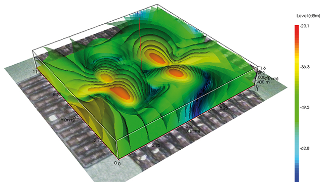
Figure 3 The ICS 105 is connected to a spectrum analyser and a PC for the measurement. The CS scanner measurement and evaluation software controls the ICS 105 and records the measurements.The CS scanner software developed by Langer EMV-Technik GmbH lets the user read out the measured data from a spectrum analyser, show this graphically (in 2D or 3D, Figure 4) as well as store and output this (CSV file). The software can also be used to control the most important spectrum analyser settings (Figure 5).
Figure 4 3D volume scan generated by the ChipScan scanner softwareFigure 5 User interface of the CS scanner software. Right: operator panel for the connected spectrum analyser Top left: measurement diagram and trace manager to log all of the measurements carried out.
ICS 105 scanner with ChipScan scanner control and analysis software offers:
– Triggering via a PC/laptop
– Zero-point position, manual or script-based movement of the near-field microprobe
– Reading out the measured data from a spectrum analyser
– Graphic presentation of the measured results in 2D or 3D
– Output in csv and image files
– Automated measurements on the IC:
– Surface scans over ICs in accordance with IEC61967-3
– Volume scans over ICs
– PIN scans
For more information, visit http://www.langer-emv.com/.
