
An Approach Using EMC Standards
This article describes an approach for hardening high-voltage power substation control electronics from high-altitude electromagnetic pulse (HEMP) that would occur if a nuclear weapon were detonated in space. While we hope that this type of electromagnetic event never occurs, it is a possibility, and the impact on unprotected electronics and the power grids that they control could be severe. In the case of HEMP, a single high-altitude nuclear burst could expose thousands of power substations to high-frequency transients within one power cycle, creating essentially a simultaneous distributed event for which the power grid was not designed.
While the emphasis for this article will be on the protection from early-time (E1) HEMP, it will also discuss the additional efforts that can be made to protect the electronics from intentional electromagnetic interference (IEMI) produced by electromagnetic weapons. By considering both the E1 HEMP and IEMI together, we cover the main high frequency transient high-power EM (HPEM) threats that have become important in recent years.
As described in the work in IEC SC 77C, while high power electromagnetic (HPEM) disturbances are low probability events, they can be protected against with existing protection technology, and often at low cost. The field of electromagnetic compatibility (EMC) is well established, and methods for shielding against electromagnetic fields and attenuating conducted transients are widely known. The main issue is to determine the requirements for these protective elements as they relate to E1 HEMP and IEMI.
This article focuses on the fact that the electronics found in the control houses of electric power substations are already exposed to high levels of natural power system EM transients and are therefore required to have immunity against high levels of radiated and conducted transients. The major generic EMC standards for establishing immunity tests and test levels for electronics placed in control houses are set forth in IEC 61000-6-5 [1]. By considering the basic immunity of the electronics in the control houses for EMC and the external HEMP and IEMI radiated field waveforms and their coupling to external cables outside of the control house and internal cables (thereby creating conducted transient disturbances), protection methods can be established. The recently developed IEC 61000-5-10 [2] provides different strategies for protection for both new and retrofit applications, relying on several other published IEC SC 77C standards.
In this article, we’ll first review the basic HEMP and IEMI electromagnetic waveforms as discussed in our previously published article in In Compliance Magazine [3]. Next, we’ll describe the basic layout of high voltage substations and the electronics found in a substation control house. Then, we’ll discuss the EMC immunity requirements for the control electronics and how these can be leveraged to determine the specialized HEMP/IEMI protection methods. Following this discussion, we’ll share and describe the techniques for rapidly assessing the existing shielding and penetration protection of an existing control house. Finally, we’ll discuss some of the protection options available.
HEMP/IEMI Environments
As described in [3], high-altitude HEMP is defined as three separate waveforms as shown in Figure 1. The waveforms are described as early-time, intermediate-time, and late-time waveforms, and they are also described more briefly as E1, E2, and E3 HEMP. The IEC has standardized these waveforms, which can be found in IEC 61000-2-9 [5]. In this article, our focus will be on E1 HEMP, as the electronics in the control house are most impacted by this high-frequency waveform. There are possible effects on these electronics that could occur due to harmonics in the power supply system attributable to E3 HEMP, but this aspect is under evaluation in separate research projects.
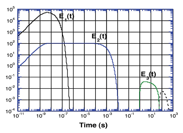
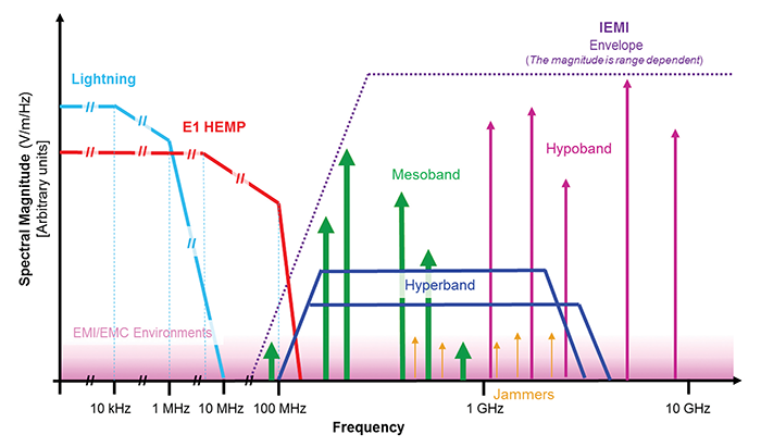
Figure 2 describes in the frequency domain the relationship between early-time (E1) HEMP and IEMI environments that can be produced from electromagnetic weapons. It also indicates at lower frequencies the typical levels of lightning electromagnetic fields from very near cloud-to-ground strikes. It is important to understand that, while lightning currents and fields are very energetic, they do not extend significantly above 1 MHz in frequency content, as do both the E1 HEMP and IEMI. This means that most grounding and bonding methods used for lightning are not sufficient for the higher frequency content E1 HEMP and IEMI. This will be discussed later in this article.
Layout of High Voltage Substations and Control Houses
Power substations are built for transmission grids at high voltages above 100 kV and, in the United States, at extra high voltages (EHVs) above 345 kV. A majority of the power moved by transmission power lines in the U.S. is at a voltage of 500 kV. These higher voltages move high power levels over long distances from power plants to areas where power is needed by industry and homes (this is still true today, despite local renewable power sources). Inside the power substation fence, the high voltages are stepped down to lower high or medium voltages for distribution to customers.
There are also distribution substations found within towns and cities, but the focus of this article is on the transmission substations due the much higher amount of power passing through the substation. The loss of power flowing through a few transmission substations in a region can create a severe power supply/load imbalance that can result in a power blackout.
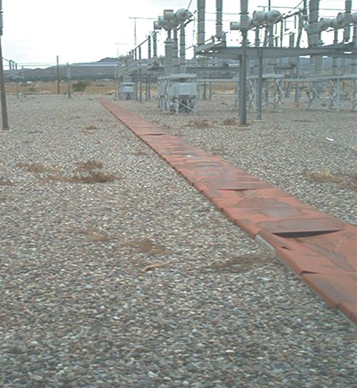
As long transmission lines arrive at a power substation, there are sensors on each line to monitor the current and voltage levels arriving at the substation (known as CTs and VTs). These sensors have low voltage cables attached that run (as shown in Figure 3) to a control building (often referred to as a control house), where these currents and voltages are monitored using mainly solid-state protective relays.
As a simple example, if the voltage on a line decreases rapidly and the current increases sharply, this could be an indication of a line being grounded to a tree, and the relay receiving this information will send a signal to a circuit breaker (along another cable) to disconnect the power line from the step-down transformer to avoid damage. These relays are programmed ahead of time to determine what levels will trigger such a response, and actions are taken automatically without human intervention. These protection relays are therefore critical to the operation of a power substation and the overall power grid.
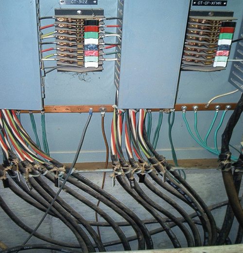
Inside the control houses, most of the control cables used today are not shielded. However, there are often ground wires or cable meshes that are grounded to an internal grounding system inside the building (see Figure 4). From an E1 HEMP or IEMI point of view, grounding cables inside of a building is not the best approach as the induced currents from E1 HEMP and IEMI will flow on these cables inside the building and will create electromagnetic fields that can couple to the internal wiring and to the nearby electronics. In addition, the use of wires is not effective in grounding high frequency transients as the inductance of a grounding wire is more important than the wire resistance. As we’ll discuss later, using shielded control cables and grounding them outside of a building will greatly reduce the conducted and radiated EM disturbances that can create failures to the operating solid-state equipment.
It is important to understand that for both E1 HEMP and IEMI the electromagnetic transients are created external to the building. There, they couple to external cables, external antennas, and interact with the walls of the control house to penetrate to the inside through apertures (for air flow and doors for example) and through nonmetallic walls such as concrete. Figure 5 illustrates the types of aspects that should be considered for the penetration of external fields and voltages into a control house.
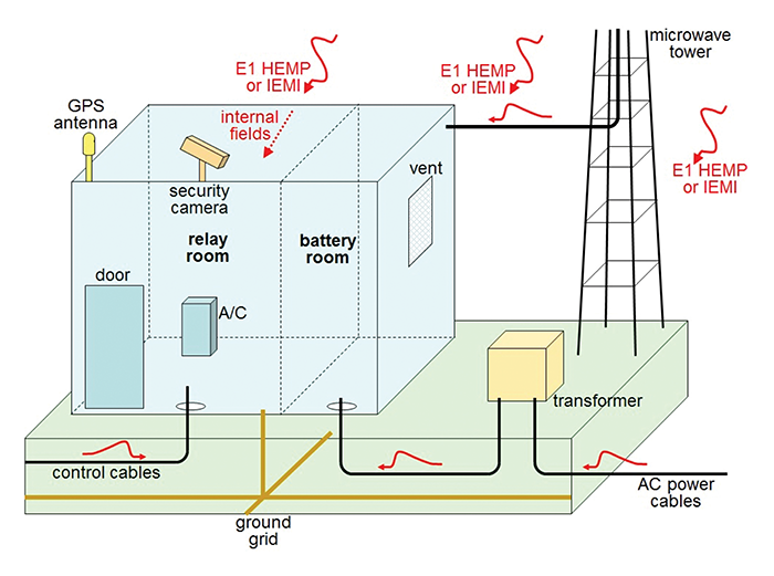
However, it is important to note that not all of the penetration features are equally important for E1 HEMP and for IEMI. For example, the coupling of E1 HEMP to buried cables is much stronger than for IEMI, as the IEMI fields at higher frequencies are significantly attenuated in the ground. On the other hand, wiring above the ground is well exposed to IEMI environments, and apertures in the walls of the building allow more penetration of the IEMI environments. GPS antennas are also at risk due to jamming by IEMI. Later in this article, we’ll address in greater detail the protection options for these different types of radiated and conducted penetrations.
EMC Immunity Requirements for Control House Equipment
It is well established that the normal electromagnetic environments are severe situations for electronics in power control houses due to the nearby presence of high voltage and current lines. While it might appear that the main EM disturbances are associated with 50 or 60 Hz, it turns out that connections and disconnections of high voltage circuits create a disturbance known as the electric fast transient (EFT) in low voltage control cables. The IEC test waveform for the EFT [7] is a 5/50 ns (10-90% rise time/50-50% pulse width) which is repeated at a frequency of up to 100,000 times per second. It is also noted that this same waveform is recommended for testing of conducted E1 HEMP transients (although only 1 or 2 pulses) [8], as it represents a typical conducted E1 HEMP waveform.
In addition, due to the presence of transmission lines and busbars within a substation, there is the possibility of nearby lightning strikes. Cloud-to-ground lightning strokes will create currents that will flow to the electronics through the control cables, and the IEC recommends a 1/50 microsecond voltage transient to test the low voltage electronics inside of a control house [9]. It is important to note that according to IEC 61000-6-5 [1] power substation equipment should be tested to the highest levels of these two tests due to their severe EM environment. IEC 61000-6-5 recommends many additional EMC immunity tests to be performed for power system electronics, but these two pulsed tests are the most important for their relationship to E1 HEMP and IEMI.
While it is important to reduce the external radiated and conducted environments associated with E1 HEMP and IEMI, we wish to make the important point that, due to the severe EMC tests required for the individual electronic boxes, the reductions required for the radiated and conducted transients from E1 HEMP and IEMI are not as large as would be required for commercial or industrial electronics.
Assessment Methods to Evaluate EM Status of Control Houses
For existing buildings, it is important to evaluate the situation with respect to the attenuation of electromagnetic fields and conducted currents and voltages as they relate to the specific threats of E1 HEMP and IEMI. Two initial aspects need initial attention: 1) the determination of the shielding effectiveness of the control house itself; and 2) the physical examination of the cables as they enter the building. Fortunately, most power companies use specific methods to construct their control houses, and specific types of control cables including trenches between the high voltage power lines and the control houses. In addition, power companies tend to ground and bond their cables in similar fashions. Of course, there can be older control houses still operating within a power company’s region, and there can also be newer building and cable designs that are being introduced to their system based on new communications protocols for Smart Grid applications.
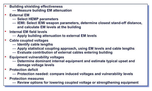
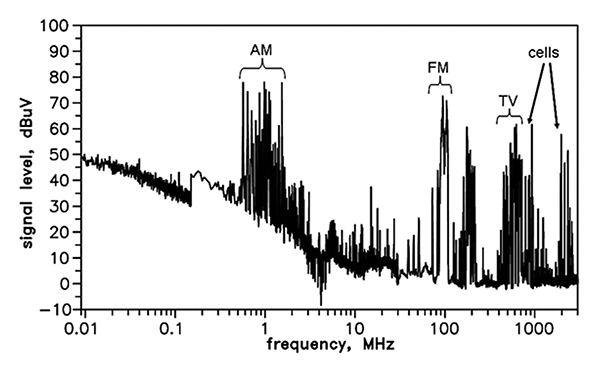
Figure 6 presents the steps required to perform a complete assessment for a control house for both E1 HEMP and IEMI. The first step is to evaluate the shielding effectiveness of the control house from1 to ~100 MHz for E1 HEMP and from ~100 MHz to ~5 GHz for IEMI. There is a relatively new method available [10] to assess the shielding effectiveness of operating facilities with shielding levels below 50 dB, known as the commercial radio signal assessment method. This method uses measurements of local AM, FM, digital TV, and cellular signals both inside and outside of the building to estimate the amount of attenuation present (see Figure 7 as an example of external signals which are well above the noise).
Through frequency domain to time domain translations, this process can convert any external time domain transient to an internal room time domain transient, as long as the frequency range information acquired is appropriate. This also does not require Federal Communications Commission (FCC) approval of special transmitters and allows a proper plane wave simulation of E1 HEMP conditions, as even at 1 MHz the wavelength is 300 meters, which would require a transmitter standoff of much greater than this distance. Evaluations of this technique have been performed with good results and have been applied to over 100 control houses in the past 10 years.
Once the shielding effectiveness has been evaluated over the frequency range of interest, one must then define the E1 HEMP and IEMI waveforms to be applied. IEC 61000-2-9 [5] provides a good example for E1 HEMP, and IEC 61000-2-13 provides several examples for IEMI threats [11]. In addition, since the IEMI EM weapon threat is a local threat, the closest approach to the control building needs to be evaluated. Satellite mapping tools can be used for this purpose.
Once the external EM threats are defined, the internal time field waveforms can be developed using the measured EM attenuation information. The next step is to evaluate the currents and voltages coupled to the internal wiring using coupling evaluations based on random orientations and polarizations performed for different cable lengths. Then, a probabilistic method can be used to select worst case or average levels of coupling.
In addition to this coupling to wiring by fields penetrating the building, one must also consider the coupling to external control cables and other cables penetrating the building such as conduits from security cameras and antennas. These levels can vary considerably based on the grounding and bonding of these cables as they enter. Also, for the control cables in trenches, IEC 61000-2-10 [12] provides information on the levels of E1 HEMP currents and voltages appropriate for above ground and buried cables.
Once the coupled currents and voltages appearing inside the control house have been determined, these need to be compared to the immunity of the equipment. Fortunately, the standard IEC 61000‑4‑4 EFT waveform for EMC can be used as a proxy. It requires a fast ~4 kV pulse (5/50 ns) for power system equipment [7]. Recent testing has found that most protective relays satisfy this requirement, and some will be able to withstand higher levels, but it is difficult to establish specifically upset levels for all situations. Therefore, it is recommended that the immunity level for the internal electronics using the EFT waveform be used to determine whether any additional protection will be required for E1 HEMP or IEMI (last step of assessment process in Figure 6).
Protection Options for Control Equipment
Once the assessment process is complete (and it must be done separately for both E1 HEMP and IEMI), there are a range of protection techniques that can then be deployed (see Figure 8). In particular, one needs to compare the levels of currents and voltages induced on cables inside of the building from the penetrating EM fields through the building walls to the current and voltage levels that are due to the external cable penetrations. If the external cables currents and voltages are small due to good bonding and grounding techniques, then the focus must be on reducing the internal fields coupling to the cables. If the reverse is true, then the focus needs to be on the external cables.
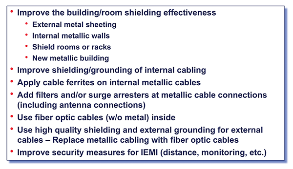
Since control houses are typically not very large and are often constructed of reinforced concrete, it is possible to add external metallic sheeting or internal shielded wallboard to increase the shielding effectiveness of the building. Also, if there is some extra-sensitive equipment inside the building, a shielded rack or room can be built inside. If there is a plan to upgrade the internal electronics to newer technologies, a last option would be to remove the existing building and rebuild it as a metal building, which tends to provide higher levels of protection. Note that this does not require a perfect 80-100 dB building, but rather a typical bolted metal building which can be built off site and transported to an existing concrete pad.
Separately, since the resistive grounding for lighting transients is often not sufficient, all external cables should be evaluated to ensure that they are grounded properly for high frequency transients. For shielded control cables, one should ground them before entry into the building to metallic surfaces (using U clamps, not ground wires). If the building is of concrete construction, then a metal plate can be mounted on the side of the building and connected to the grounding grid. Ideally the bonding should take place below the surface of the earth, so the cable itself is not exposed in the air after the bonding.
This procedure has been applied with good success for several existing control buildings. Of course, it is recommended that, if unshielded cables are used for the control cables, these should be converted to shielded cables or fiber optic cables (according to the new power substation communications standard IEC 61850-3 [13]). A recent design has used fiber optic control cables according to this new IEC standard, reducing its vulnerability to HEMP and IEMI [14].
Once the reductions of internal wire currents and voltages are completed, it is still possible that the reductions won’t be sufficient with respect to the immunity of the equipment. In these cases, it may be possible to use internal wire metallic conduits, ferrites and, in the worst case, surge arresters. The latter is not the best choice as there will be a need to test and replace surge arresters over time. Also surge arresters designed for very fast transients are not easy to find and may be very expensive (most lightning surge arresters operate too slowly to be effective).
A final point to mention is that for the IEMI threat, distance between the attacker and the control house is very important, as the fields fall off rapidly from any EM weapon. All substations are fenced around the outside to keep the public away from hazardous electrical voltages, currents, and fields. In fact, many substations are now using solid fencing instead of chain link to reduce the potential threat related to attacks using firearms. A solid material will provide addition attenuation to an attacker at the fence position, and any effort to move further back to find an elevated position to illuminate a control house will extend the distance and reduce the field on target. As part of IEMI assessments, I have participated in evaluating the best locations for line-of-sight attacks on multiple control houses, and often the fields that would be directed on a control house can be reduced by factors of 2-10 based on extended ranges and opaque fencing.
Summary
This article has described the basic threat information for both E1 HEMP and the EM weapon fields that can create IEMI. We have described the special problem of the high voltage control houses found within transmission substations, and the importance of the reliable operations of the electronics inside.
Although the electronics inside the control houses are protected from natural high voltage transients, the frequency content and levels of the E1 HEMP and IEMI fields exceed the normal EMC protection methods found in these buildings today. This is mainly due to the fact that the EM shielding of the control houses is much higher for lightning fields than it is for E1 HEMP/IEMI, and the cable grounding techniques are only adequate for lightning.
This means that an assessment method is needed to evaluate the situation for existing control houses and their control cable system. In this article, we have detailed a method that has been applied to over 100 control house buildings. We have also presented several methods of improving the protection of these buildings from E1 HEMP and IEMI by examining different grounding methods, the use of shielded cables, the use of ferrites, etc., through laboratory and installation measurements.
Given that there are multiple methods available to reduce the susceptibility of the important equipment inside the control houses, it is possible to evaluate the effectiveness and the cost of these options. In addition, for those power companies who are upgrading the electronics and communications protocols in their substation control houses, it is possible to develop a specific protection approach that can be replicated over and over.
One last point I want to emphasize is that, while E1 HEMP and IEMI are very unusual and hopefully low probability threats, the protection methods to be used are found within the EMC toolbox. Ultimately, it is a matter of defining the requirements for protection as opposed to developing new protection methods.
References
- IEC 61000-6-5 Ed. 1.0 (2015-08-21): Electromagnetic compatibility (EMC) – Part 6-5: Generic standards – Immunity for equipment used in power station and substation environment.
- IEC/TS 61000-5-10 Ed. 1.0 (2017-05-18): Electromagnetic compatibility (EMC) – Part 5-10: Installation and mitigation guidelines – Guidance on the protection of facilities against HEMP and IEMI.
- William Radasky, “Protecting Industry from HEMP and IEMI,” Feature article in In Compliance Magazine, November 2018.
- Kenneth Smith, “Plot of analytic formulas selected by the IEC to describe the three phases of the high-altitude electromagnetic pulse,” Metatech Corporation, April 1992.
- IEC 61000-2-9 Ed. 1.0 (1996-02-19): Electromagnetic compatibility (EMC) – Part 2: Environment – Section 9: Description of HEMP environment – Radiated disturbance.
- Richard Hoad, “Frequency domain comparison of IEMI environments with other transient waveforms,” Personal Communications, November 2016.
- IEC 61000-4-4, Electromagnetic compatibility (EMC) – Part 4-4: Testing and measurement techniques – Electrical fast transient/burst immunity test.
- IEC 61000-4-25 Ed. 1.2 (2019-12-11): Electromagnetic compatibility (EMC) – Part 4-25: Testing and measurement techniques – HEMP immunity test methods for equipment and systems. Basic EMC publication
- IEC 61000-4-5, Electromagnetic compatibility (EMC) – Part 4-5: Testing and measurement techniques – Surge immunity test
- Edward Savage, James Gilbert and William Radasky, “Expedient Building Shielding Measurement Method for HEMP Assessments,” IEEE Transactions on Electromagnetic Compatibility, Vol. 55, No. 3, June 2013,
pp. 508-517. - IEC 61000-2-13 Ed. 1.0 (2005-03-09): Electromagnetic compatibility (EMC) – Part 2-13: High-power electromagnetic (HPEM) environments – Radiated and conducted.
- IEC 61000-2-10 Ed. 1.0 (1998-11-24): Electromagnetic compatibility (EMC) – Part 2-10: Environment – Description of HEMP environment – Conducted disturbance.
- IEC 61850-3 Ed. 2.0 (2013-12): Communications networks and systems for power utility automation – Part 3: General requirements
- Eric Easton, Kevin Bryant, and William Radasky, “Design approach for HPEM mitigation for electrical substations,” IEEE EMC Symposium, Reno, Nevada, July 2020, pp. 439-441.