The 21st century as we know it, truly reflects the age of technology. Every aspect of life today is encompassed by the use of some sort of microprocessor based electronics intended to simplify tasks, to improve processes, and improve efficiency. Electronics are used to communicate with loved ones, manage finances, fly aircraft, even save lives. As greater advances in technology are achieved, electronics are found controlling more important safety critical functions at an exponential rate. Although electronics have provided us with obvious benefits, the increasing reliability on electronics has elevated our vulnerability to the effects electromagnetic pulses.
An electromagnetic pulse (EMP) is defined as a high amplitude, short duration, broadband pulse of electromagnetic energy which can have devastating effects on unprotected electronic equipment and systems.
EMPs are historically known as the electromagnetic effects following a nuclear blast occurring at high altitudes (also known as HNEMP). The first discovery of the HNEMP incident was made by the U.S. in 1958 during a series of high-altitude atmospheric tests. The most noted was during the detonation of the nuclear payload named “Starfish Prime,” over the Pacific Ocean over 800 miles away from Hawaii. Although the distance from the explosion was so great that physical detection was not possible, it caused a severe electromagnetic pulse which traveled distances much further than the shock wave and blast effects. The resulting electromagnetic pulse disrupted radio stations, damaged electrical equipment, and even blew out street lights throughout Hawaii.
To fully explain the physics behind how EMPs are created extends beyond the scope of this paper, but can be simplified to a short sequence of events:
- A nuclear payload is launched and detonated at an altitude within or above the earth’s atmosphere.
- During the explosion, Gamma rays (high energy photons) are rapidly released in all directions from the blast.
- These gamma rays interact with air molecules in the earth’s atmosphere which creates electromagnetic energy.
- This interaction process is called the “Compton’s Effect.”

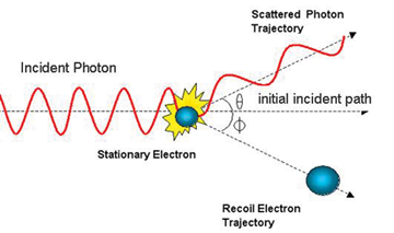
When a gamma ray “incident photon” collides with an atom in the atmosphere, it knocks a stationary electron free on a trajectory away from the blast.
These electrons “Compton’s electrons” being smaller than their corresponding positively charged atom travel at a higher rate of speed rapidly increasing the charge separation distance between them.

This separation time is expected to define the EMP rise time to peak voltage. The electrons quickly recoil back to their proton to conserve energy “Compton’s recoil electrons.” This recoil time is expected to determe the EMP fall time from peak voltage much like that of charging and discharging a capacitor, and closely resemble the characteristics of an electrostatic discharge (ESD). Typical pulse rise times can range from 2 to 10 nanoseconds (2 – 10 billionths of a second) fall time duration’s range from 100 ns to 20 microseconds (up to 20 millionths of a second). These pulse characteristics disperse energy across a broad spectrum ranging from 50 kHz to 500 MHz. However, the majority of the pulse energy resides in the frequency spectrum of 10MHz-100MHz which is considered the most predominant operating range for most microprocessor equipment and provides the greatest risk for vulnerability. Peak field strengths are estimated to reach into the 100s of thousands of volts.

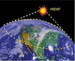
The exposure radius of a high altitude EMP commonly known as the “disposition region” is determined by three main elements, 1: Height of the blast, 2: size of the blast, and 3: type of explosive (kinetic energy). In general terms, the higher the explosion is, the greater the disposition region becomes. The size and type of the blast will determine the magnitude of the EMP. Theoretically, the size of the EMP disposition region is only limited by the curvature (horizon) of the planet.
To better understand the magnitude of this theory, it has been speculated that if a 100 Megaton nuclear payload was detonated at a height of approximately 300 miles over central United States, the EMP disposition region could effectively envelope the entire country. A pulse from such a height would extend to the visual horizon of the planet as seen from the burst point perspective.

What is the risk of a nuclear EMP attack? The Nuclear Non-Proliferation Treaty (NNPT) enforced since 1970 intended to limit the spread of Nuclear weapons currently includes 189 states, 5 of which are recognized as nuclear weapon states: U.S., Russia, the U.K., France and China. These states comprise the five permanent members of the UN Security Council). However, four non-parties of the treaty are known to or believed to possess nuclear weapons. India, Pakistan, Israel, and North Korea have openly tested and declared that they possess nuclear weapons. Israel claims ambiguity regarding its nuclear weapon program, while North Korea acceded to the treaty, violated it, and withdrew from it in 2003. The Comprehensive Nuclear-Test-Ban Treaty (CTBT) bans all nuclear explosions in all environments, for military or civilian purposes. It was adopted by the United Nations on 10 September 1996 but it has not yet entered into force. Advocates of nuclear disarmament say that it would lessen the probability of nuclear warfare from occurring, but critics say that it would undermine deterrence. Until CTBT is strictly enforced, and as creation nuclear weapons continue, the risk of a NEMP attack is expected to grow.

On a smaller scale, highly effective non-nuclear EMP technologies are progressively being developed worldwide. These technologies are classified as “Direct Energy Weapons” and are currently being used today by our U.S. armed forces, and state and local police departments. Direct energy weapons travel to the target at the speed of light much like that of a conventional EMP, and are capable of graduated effects on electronics ranging from disrupting operation, to permanent damage, and complete destruction.
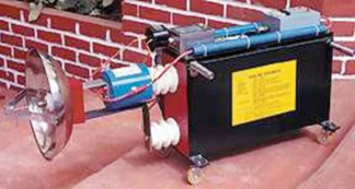
A prime example of this technology is the arc discharge EMP generator. These devices use high voltage and massive energy storage of capacitors which is released across a thin under rated conductor to a low impedance load or short circuit. The wire acts like a fuse opening at the peak of the high current discharge of the capacitor resulting in a massive release of broadband electromagnetic pulse of energy similar to a conventional HNEMP. These generators typically integrate a small parabolic reflector to direct and focus the pulsed energy towards a target.

Another example of Non-nuclear EMP technology is the Flux Compression Generator (FCG). The FCG was first demonstrated by Clarence Fowler at Los Alamos National Laboratories (LANL) in the late fifties. This technology injects a high energy pulse into a large conductive coil. At the point of peak pulse current, a small explosive charge is deployed which quickly compresses the coil to one end of the generator creating massive amounts of electromagnetic energy. The first designs were several feet in length, but through technological advances, are now reported to be roughly the size of a beer can.

With the creation of non-nuclear direct energy weapons, and the existing use of the devices on the battle field, as well as civilian non-combat environments, the need to protect electronic equipment is at an all time high. The U.S. Military has been evaluating the effects of electromagnetic pulses on equipment for the past 50 years, and have developed protective design guidelines and hardening techniques currently used today.
MIL-STD-461F provides test methodology and screening levels for determining a device’s immunity to EMP from a radiated and conducted standpoint. The coupling modes onto the equipment enclosure and its interconnecting cabling can be complex, therefore are evaluated separately.
The RS105 test method specified in MIL-STD-461F addresses the risk of radiated exposure to an EMP event. RS105 testing is generally applicable for equipment installed in exposed and partially exposed environments. The U.S. Navy requires RS105 testing for nearly every installation platform, surface ships, submarines, and aircraft, to ground applications.
The RS105 pulse characteristics consist of a fast rise time, short pulse duration, and high amplitude which resemble those of an actual EMP. Peak field strengths of 50 kV/m are specified for exposed equipment. However, tailoring the peak field levels are often required for partially exposed installations due to the attenuated effects provided by enclosures such as the deckhouse structure, or hangar doors. For example, equipment installed near deckhouse apertures are required to meet the external stress reduced by the shielding effectiveness of that specific aperture or by the 40 dB of electromagnetic shielding provided by the deckhouse structure, whichever is less.

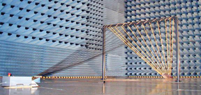
RS105 testing performed with a transmission line connected to a transient pulse generator. The generator and the far end of the transmission circuit are commonly bonded to reference ground. This connection provides a return path allowing current flow allowing for the generation of electromagnetic fields. The equipment under test is then installed underneath the transmission line within the predetermined uniform field area.
The field developed between the transmission line and the ground plane consists of large differential voltage and current fields. To ensure a proper uniform field distribution area, RS105 requires that transmission line length, and width are at least twice that of the equipment being tested and at least three times the height.

Prior to testing the uniform field is verified along a 5 point vertical grid. The results taken at each point are verified to be within 6dB (in terms of voltage) of each other, and greater than the specified test limit (no less than 50,000 v/m).
The purpose of RS105 testing is not to damage the equipment, but to determine its immunity threshold to the electromagnetic pulse. This is performed by starting at 10% of the peak field level and gradually increasing field until susceptibility is determined or the specified peak field level is reached. It is important to note that RS105 evaluates the equipment enclosure’s ability to attenuate and withstand the effects of an EMP, not its cabling. The RS105 test setup requires that all metallic interconnecting cabling including power input lines are routed in shielded conduit and/or underneath the groundplane to minimize coupling.
The MIL-STD-461 CS116 test method evaluates the coupling effects of EMP on metallic interconnecting lines. The intent of this test is to ensure the equipment’s ability to withstand conducted damped sinusoidal transients, excited by platform switching operations, indirect effects of lightning, and EMP. The minimum set of test frequencies includes 10 kHz, 100 kHz, 1 MHz, 10 MHz, 30 MHz, and 100 MHz. In accordance with MIL-STD-461F, CS116 testing is applicable for all installation platforms and procurement agencies with limited applicability for submarines. Similar to RS105, CS116 testing is not to damage the equipment, but to determine its immunity threshold to the electromagnetic pulse. This is performed by starting at 10% of the peak field level and gradually increasing field until susceptibility is determined or the specified peak field level is reached. One important aspect to note about the testing method is that the transient signals are inductively coupled to each line. The amount of voltage and current induced onto each line is dependent on its impedance. Higher impedance lines will allow for greater voltages to be achieved at lower currents, where low impedance lines such as shielded cabling, will achieve greater currents at lower voltages. To avoid excessive over testing, pre calibration of the injected currents into a 100 ohm loop impedance is performed, and the currents induced onto each line are monitored. As mentioned, test levels are gradually increased until equipment susceptibility is detected, the current limit is achieved, or the generator setting determined during the 100 ohm calibration are reached.
In summary, the effects of electromagnetic pulses on electronics can be severe, but poses an even more devastating threat to the processes and infrastructures that they support. Designing equipment and systems to withstand the effects of EMPs now will reduce the impacts of potential EMP attacks on our electronics in the future. ![]()
Jeffrey Viel is a former U.S. Marine and a highly recognized electromagnetic interference and compatibility test engineer with over 18 years of experience. Jeffrey is currently employed as the EMI/EMC business development manager for National Technical Systems Mass Ops division, and has worked for NTS for approximately 10 years. Jeffrey also supports NTS engineering services as a senior technical consultant providing design for test, mitigation, and training services for the department of defense (DoD), aerospace, telecommunications, railway, nuclear power, and renewable energy industries. He is recognized by the Practicing Institute of Engineering, Inc (PIE) as a competent EMI/EMC course instructor for the New York City Transit.
