“Factory ESD control is expected to play an ever-increasing critical role as the industry is flooded with even more HBM (Human Body Model) and CDM (Charged Device Model) sensitive designs.”
Electrostatic discharge (ESD) is the hidden enemy within your factory. You cannot feel or see most ESD events, but they can cause electronic components to fail or cause mysterious and annoying problems.
There are two types of ESD damage: 1. catastrophic failures, and 2. latent defects. By definition, normal quality control inspections are able to identify catastrophic failures, but are not able to detect latent defects.
In general, modern electronics are more susceptible to ESD; that is their withstand voltages are lower. This is due to the drive for miniaturization and faster operation. Thus the semiconductor circuitry is getting smaller.
What’s happening currently? The width of electronic device structures continues to get smaller. Intel began selling a 32nm processor in 2010 that was 0.032 micrometer, equal to 0.000032 millimeter or 0.00000128 inch.
The ESD Association’s latest white paper, Electrostatic Discharge (ESD) Technology Roadmap – Revised April 2010, [1] (see www.ESDA.org) forecasts increased ESD sensitivities, continuing the recent trend,with the result that “the ICs became even more sensitive to ESD events in the years between 2005 and 2009. Therefore, the prevailing trend is circuit performance at the expense of ESD protection levels.” The white paper’s conclusions include:
- “With devices becoming more sensitive through 2010-2015 and beyond, it is imperative that companies begin to scrutinize the ESD capabilities of their handling processes. Factory ESD control is expected to play an ever-increasing critical role as the industry is flooded with even more HBM (Human Body Model) and CDM (Charged Device Model) sensitive designs. For people handling ESD sensitive devices, personnel grounding systems must be designed to limit body voltages to less than 100 volts.”
- “To protect against metal-to-device discharges, all conductive elements that contact ESD sensitive devices must be grounded.”
- “To limit the possibilities of a field induced CDM ESD event, users of ESD sensitive devices should ensure that the maximum voltage induced on their devices is kept below 50 volts.”
- “To limit CDM ESD events, device pins should be contacted with static-dissipative material instead of metal wherever possible.”
Dr. Terry L. Welsher’s article, “The ‘Real’ Cost of ESD Damage” [2], includes the observation that “Recent data and experience reported by several companies and laboratories now suggest that many failures previously classified as EOS (Electrical Overstress) may instead be the result of ESD failures due to charged board events (CBE). … Some companies have estimated that about 50% of failures originally designated as EOS were actually CBE or CDE (charged device events).”
ANSI/ESD S20.20 [3], the ESD Association document covering the development of an ESD control program, lists numerous ESD Protected Area (EPA) ESD control items. Each company can pick and choose which recommendations are appropriate for its program. “The selection of specific ESD control procedures or materials is at the option of the ESD Control Program Plan preparer and should be based on risk assessment and the established electrostatic discharge sensitivities of parts, assemblies, and equipment.” [ANSI/ESD S20.20-2007 Annex B] “An EPA (ESD protected area) shall be established wherever ESDS (ESD Sensitive) products are handled. However, there are many different ways to establish ESD controls within an EPA. Table 3 lists some optional ESD control items which can be used to control static electricity.” [ANSI/ESD S20.20-2007 section 8.3 ESD Protected Areas (EPAs)]
There are companies with good ESD control programs that are pleased with their quality and reliability results. But to maintain that level, they would be wise to consider ESD control program improvements. Now might be a good time to do that.
Human Body Model (HBM)
Part of the challenge may be the need to handle, for the first time, electronics having a HBM Class 0 withstand voltage. Per the ANSI/ESD S20.20 Foreword:
- This standard covers “electrical or electronic parts, assemblies and equipment susceptible to damage by electrostatic discharges greater than or equal to 100 volts Human Body Model (HBM)”
- “When handling devices susceptible to less than 100 volts HBM, more stringent ESD Control Program Technical Requirements may be required, including adjustment of program Technical Element Recommended Ranges.”
The Component Classification Level Table 3 from the updated standard ANSI/ESDA/JEDEC JS-001-2011, Electrostatic Discharge Sensitivity Testing Human Body Model (HBM), [4] (Table 1) has divided the Class 0 classification into two withstand voltage levels, with Class 0A being less than 125 volt sensitivity and Class 0B being 125 to less than 250 volts.
| Classification Voltage Range (V) | |
| 0A | < 125 |
| 0B | 125 to < 250 |
| 1A | 250 to < 500 |
| 1B | 500 to < 1000 |
| 1C | 1000 to < 2000 |
| 2 | 2000 to < 4000 |
| 3A | 4000 to < 8000 |
| 3B | ≥ 8000 |
Table 1: Table showing HBM ESD component classification levels from ANSI/ESDA/JEDEC JS-001-2011
If handling class 0A items, or less than 125 volts, program improvements are called for. Basically, to control the environment to decrease the probability of ESD damage in class 0A situations, involves increasing ESD protective redundancies by adding EPA ESD control items and ensuring that they are working properly by increasing the frequency of compliance verifications of those ESD control items.
Tackling HBM
Personnel grounding has historically been the foundation of most ESD control programs. Back in the early 1980s, the first standard written by the ESD Association was on wrist straps. Therefore, many companies mistakenly believe that operator grounding is no longer an issue. But there are areas of operator grounding where improvement should be considered.
While ANSI/ESD S20.20 has set the maximum upper limit of 35 megohms resistance for personnel grounding via a wrist strap system, consider lowering that upper limit within your ESD control plan to 10 megohms. The ESD Handbook ESD TR20.20 Figure 14 “Relationship between Body Voltage and Resistance to Ground” graph [5] (Figure 1) shows this would typically reduce body voltage from about 100 volts to less than 40 volts.

Figure 1: Graph setting the personnel grounding guideline from ESD Handbook ESD TR20.20 Figure 14 “Relationship between Body Voltage and Resistance to Ground”
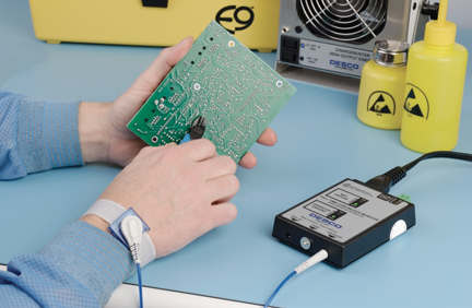
In addition, the use of continuous monitors should be evaluated. Wrist strap continuous monitors (Figure 2) will provide the benefit of detecting intermittent fault conditions, such as a coil cord wearing out or an operator having the wristband too loose. These will often not be detected by daily or even twice daily touch-testing. There are new models with technology that, besides monitoring the ground of operators and worksurfaces, will also alarm when body voltage exceeds 2.5 volts and alert the operator to actions, movements, or materials that are causing the operator to become charged.

Figure 2: Wrist strap and continuous monitor
If grounding personnel is achieved by use of a flooring/footwear system, heel grounders should be replaced with sole or full coverage grounders (Figure 3). The measurement of resistance alone is not sufficient to measure the effectiveness of the operator/flooring/footwear system. We see many companies with a conductive tile floor that measures mid-10^5 ohm resistance to ground and the operators are wearing foot grounders on each foot that passes the touch-testing. But what peak voltage on the body is generated? Over the years, there have been independent studies that have shown that with conductive flooring measuring less than 1 x 10^6 ohm resistance and footwear that measure low 10^6 ohm resistance, the following body voltage spikes were recorded when the ANSI/ESD STM97.2, Floor Materials and Footwear – Voltage Measurement in Combination with a Person [6] test was performed:
- using heel grounders, body voltage spikes to ±250 volts
- using sole grounders, body voltage spikes were reduced to ±75 volts or less
- using full coverage grounders, body voltage spikes were reduced to ±25 volts or less.

Figure 3: Shoes with full coverage grounders and sole grounder
Basically, the greater the footwear contact surface, the higher the probability that while walking, bending, kneeling, reaching, etc. the operator will be in contact with the ESD floor.
“Procedures For The Design, Analysis and Auditing Of Static Control Flooring/Footwear Systems” by Stephen L. Fowler, William G. Klein, and Larry Fromm [7] includes, “With heel grounders, his potential dropped to 250 in one installation and 450 in the other, these being the peaks when both heels left the floor, as they did with nearly every step. When care was taken not to allow simultaneous contact loss with both grounders the values were 40 and 170 volts respectively. When he used a sole grounder, which is essentially a combination of heel and toe grounders, the peak voltage in both cases dropped below 30 volts.”
Conductive flooring less than 1 megohm (1 x10^6 ohms) is often preferable. However, if the resistance upper limit is less than 1 x 10^9 ohms, end users must add the ANSI/ESD STM97.2 test method for body voltage to the qualification of their footwear/flooring operator grounding system in order to protect the sensitive devices of today and the more sensitive devices to come. It is no longer enough to know that a standing operator is grounded. When they are working, moving around with ESDS devices and assemblies, are they generating potentially harmful body voltage spikes? In addition, ESD flooring requires maintenance to keep it clean and effective. All ESD flooring should be cleaned with a good quality ESD floor cleaner that will not leave behind an insulative residue that can raise floor resistance. Many companies also want their floors to be shiny. Today, good quality dissipative floor finish can improve durability and gloss while also reducing the charge generation characteristic of the floor to less than <50 volts.

Figure 4: Workspace with a Statguard floor finish
Charged Device Model
It may seem to some that CDM has newly arrived as a problem for ESD control programs. However, the ESD Association first published ANSI/ESD STM5.3.1 ESD Association Standard for Electrostatic Discharge Sensitivity Testing – Charged Device Model (CDM) – Component Level [8] in 1999. Basically, CDM testing has to do with “testing, evaluating and classifying the electrostatic discharge (ESD) sensitivity of components to the defined charged device model (CDM)” … “to allow for accurate comparisons of component CDM ESD sensitivity levels.”
From the JESD22-C101C Field-Induced Charged-Device Model Test Method for Electrostatic-Discharge-Withstand Thresholds of Microelectronic Components Table 3, devices are classified as follows:
CLASS I <200 volts
CLASS II 200 to <500 volts
CLASS III 500 to 1000 volts
CLASS IV >1000 volts
The importance of CDM came about primarily because of the increased use of automated component handling systems. The Foreword of ANSI/ESD STM5.3.1 states, “In the CDM a component itself becomes charged (e.g., by sliding on a surface (tribocharging) or by electric field induction) and is rapidly discharged (by an ESD event) as it closely approaches a conductive object.”
In November 2002, Roger Peirce published an article entitled “The Most Common Causes of ESD Damage” [9]. There were actually 23 causes. As the founder and president of ESD Technical Services, Roger had investigated hundreds of companies for over eight years. All 23 causes were CDM failure modes. So CDM is really not so new, It has just received a lot of attention in the last few years.
Tackling CDM
So, what are the things companies should look at to improve their ESD control program regarding CDM? It would seem to be easy: don’t slide ESDS devices and assemblies unless grounded at all times, keep insulators at least 12” away from ESDS, and don’t allow ESDS items to make contact with a conductive surface. Seems simple, but in actual application . . . not so easy.
If the ESD control program has not used ionization, that possibility should be considered. If ESDS items become charged, ionization will help neutralize the charge. The primary function of ionizers with regard to ESDS items are:
- to remove/neutralize charges from process necessary insulators, which can charge ESDS items and thus create the potential for a damaging CDM event.
Remember that the PCB substrate is a process necessary insulator and can become charged during automated handling processes. - to remove/neutralize charges from a charged, isolated/floating conductor which, when grounded, can result in a potentially damaging CDM event.
Remember that during automated handling processes, the ESDS devices on the PCB are isolated or floating conductors.
The ESD Standards Committee has a Working Group (WG-17) which is currently involved with developing a standard for process assessment to help members of the electronics community assess their manufacturing and handling processes, and determine what levels of devices their process can handle. Once one fully understands where a process is with regard to ESDS devices and assemblies, one will have a clearer picture of what actions need to be taken to further improve the ESD Control Program.
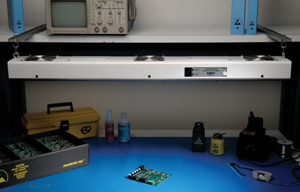
If ionizers are already in use, a company should consider reducing the ionizer offset voltage limit of ±50 volts (the required limit in ANSI/ESD S20.20) to ±25 volts and maybe less, depending on the application and device sensitivity. Discharge times are user defined and should be considered for reducing the time required to neutralize a ± 1,000 volt charge to ± 100 volts.

Figure 5: An overhead ionizer
The required limit for worksurfaces per ANSI/ESD S20.20 is less than 1 x 10^9 ohms, with no lower limit. Most companies handling electronics should be following the recommendation of the worksurface standard ANSI/ESD S4.1 [10] that the lower limit be 1 x 10^6 ohms. To combat CDM failures, all surfaces that might come into contact with ESDS items should follow, where possible, the worksurface standard and be dissipative at the 1 x 10^6 to less than 1 x 10^9 ohms range used. Items such as static shielding bags will have a higher resistance on the interior and exterior surfaces, but still must be less than 1 x 10^11 ohms.

Figure 6: A Statfree Worksurface Mat

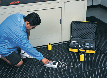
Figure 7: A surface resistance test kit

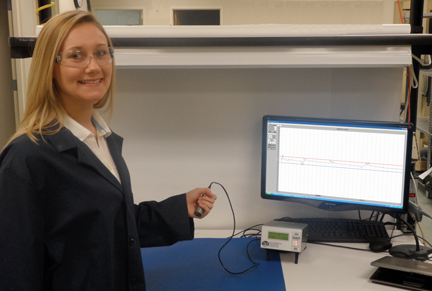
Figure 8: A volt meter and software in factory showing STM97.2 testing of voltage charge on a person (courtesy of TREK, INC.)
Other Considerations
Discipline
A significant increase in the discipline of implementing the fundamentals of ESD control, noted in the ANSI/ESD S20.20 Foreword, calls for:
- grounding all conductors in the EPA, including people.
- removing all insulators from the EPA or using ionizers for process-necessary insulators.
- packaging ESD sensitive items that go outside the EPA in packages that provide electrostatic discharge shielding.
Insulators
We encourage developing a hatred for insulators. The alternatives are to:
- remove the insulative item from the EPA.
- substitute the item with an ESD protective version (such as tape, document holders, material handling containers, plastic bottles, etc.)
- periodically treat insulative surface with a topical antistat.
- neutralize electrostatic charges using ionization.
Other ESD Control Items
Other EPA ESD control items to add to the ESD control program might include shelving, mobile equipment (carts), gloves, and/or seating.
Improve Compliance Verification Plan
- Consider greater frequency of internal audits per ESD TR53 [11].
- Use a computer data collection system for wrist straps and footwear testing, continuous monitors, and ionizers.
- Use ground continuous monitors for worksurfaces and other ESD elements.
- Test ionizers more frequently; consider self-monitoring ionizers and computer-based data collection.
- Increase testing that uses a static field meter to verify that automated processes (like auto insertion, tape and reel, etc.) are not generating charges above acceptable limits.
Improve Training
- Provide ESD-awareness training for everyone in the EPA and anyone who may come into the EPA, including suppliers.
- Improve testing to verify comprehension and training adequacy.
- Improve training on the proper use of test equipment.
- Enhance training on proper compliance verification test procedures.
Conclusion
Just to maintain its current level of quality and reliability may require a substantial improvement in a company’s ESD control program. Now is the time for improvement, as ESD sensitivity withstand voltages continue to get lower and companies may soon be handling class 0A HBM items. To combat HBM failures, improved personnel grounding is required. For example, heel grounders should be replaced with full coverage foot grounders. However, most failures are CDM. To combat CDM failures, ionization should be added or improved, and conductive surfaces should be covered with dissipative material. In general, discipline should be enhanced implementing ESD control fundamentals, compliance verification testing should be increased, and training should be improved. ![]()
References
- Electrostatic Discharge (ESD) Technology Roadmap – Revised April 2010, ESD Association, Rome, NY, April 21, 2010.
- T.L. Welsher, “The ‘Real’ Cost of ESD Damage”, In Compliance Magazine, May 2010.
- ANSI/ESD S20.20, Standard for the Development of Electrostatic Discharge Control Program, ESD Association, Rome, NY.
- ANSI/ESDA/JEDEC JS-001, For Electrostatic Discharge Sensitivity Testing Human Body Model (HBM) – Component Level, ESD Association, Rome, NY.
- ESD TR20.20, Handbook, ESD Association, Rome, NY.
- ANSI/ESD STM97.2, Floor Materials and Footwear – Voltage Measurement in Combination with a Person, ESD Association, Rome, NY.
- S.L. Fowler, W.G. Klein, and L. Fromm, “Procedures For The Design, Analysis And Auditing Of Static Control Flooring/Footwear Systems”.
- ANSI/ESD S5.3.1, Electrostatic Discharge Sensitivity Testing – Charged Device Model (CDM) – Component Level, ESD Association, Rome, NY.
- R. Peirce, “The Most Common Causes of ESD Damage”, Evaluation Engineering, November 2002.
- ANSI/ESD S4.1, Worksurface – Resistance Measurements, ESD Association, Rome, NY.
- ESD TR53, Compliance Verification of ESD Protective Equipment and Materials, ESD Association, Rome, NY.
This article has not been reviewed by the ICM Editorial Advisory Board.
| Fred Tenzer is the National Sales Manager for the Desco Brand of Desco Industries, Inc. He is a founding member of the ESD Association (ESDA) and a member of ESDA’s Standards Development since 1982. Fred is currently Vice-Chair for ESDA’s Standards Committee. Fred can be reached at Fred.Tenzer@Desco.com. Gene Felder is the Corporate Product Manager at Desco Industries. Before joining Desco, he was general manager of BW/IP International SR Engineering. Mr. Felder graduated from California State University with a B.A. in business administration and earned an M.B.A. from the UCLA Anderson School of Management. He is a member of the ESD Association serving on a number of Standards Committee working groups. Gene can be reached at Gene.Felder@Desco.com. |
