This article discusses the reflections on a transmission line at a shunt resistive and capacitive discontinuity along the line. The analytical results are verified through the HyperLynx simulations and laboratory measurements.
1.1 Reflections at the Shunt Resistive Discontinuity – Analysis
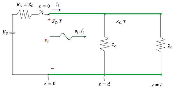
Consider the circuit shown in Figure 1.1, where the transmission line of length l has a shunt resistive discontinuity in the middle of the line, at a location z = d.

Note that the transmission line is matched at the source, and the resistive discontinuity and the load resistor values are equal to the characteristic impedance of the line.
When the switch closes at t = 0, a wave originates at z = 0, [1], and travels towards the discontinuity. At the time, t = T this wave arrives at the discontinuity. The transmission line immediately to the right of the discontinuity looks to the circuit on the left of the discontinuity like a shunt resistance equal to the characteristic impedance of the right line [2].
When this wave arrives at the discontinuity, at the time t = T, the reflected wave, vr and ir, is created, and we have a situation depicted in Figure 1.2.
The circuit in Figure 1.2 is equivalent to the one shown in Figure 1.3.
The reflection coefficient at the discontinuity is
The reflected voltage is related to the incident voltage by the reflection coefficient as
The total voltage at the discontinuity is
Since, [1],
the total voltage at the discontinuity is
The reflected voltage travels back to the source, arriving there at t = 2T. Since the source is matched to the transmission line, there is no reflection, and the total voltage at the source becomes
1.2 Reflections at the Shunt Resistive Discontinuity – Simulations
Figure 1.4 shows the HyperLynx schematic of the transmission line with a shunt resistive discontinuity.
The simulation results are shown in Figure 1.5.
1.3 Reflections at the Shunt Resistive Discontinuity – Measurements
The measurement setup is shown in Figure 1.6.
The measurement results are shown in Figure 1.7.
Note that the measurement results verify the simulation and analytical results.
2.1 Reflections at the Shunt Capacitive Discontinuity – Analysis
Consider the circuit shown in Figure 2.1, where the transmission line of length l has a shunt capacitive discontinuity in the middle of the line at a location z = d.
Note that the load resistor value is equal to the characteristic impedance of the transmission line; it is also assumed that the initial voltage across the capacitor is zero, vC (0–) = 0.
When the switch closes at t = 0, a wave originates at z = 0, [1], and travels towards the discontinuity.
The transmission line immediately to the right of the discontinuity looks to the circuit on the left of the discontinuity like a shunt resistance equal to the characteristic impedance of the right line [2]. When the incident wave arrives at the discontinuity (at the time t = T), the reflected wave, vr and ir, is created, and we have a situation depicted in Figure 2.2.
This part of the circuit is identical to the one discussed in [3], where the transmission line was terminated with an RC load. Thus, the total voltage across the capacitive discontinuity is
Equation (2.1) predicts that at t = T, the voltage at the discontinuity is zero and increases exponentially to VG /2. Let’s verify these observations through simulations and measurements.
2.2 Reflections at the Shunt Capacitive Discontinuity – Simulation
Figure 2.3 shows the HyperLynx schematic of the transmission line with a capacitive discontinuity.
The simulation results are shown in Figure 2.4.
2.3 Reflections at the RC Load – Measurements
The measurement setup is shown in Figure 2.5.
The measurement results are shown in Figure 2.6.
Note that the measurement results verify the simulation and analytical results.
References
- Adamczyk, B., “Transmission Line Reflections at a Resistive Load,” In Compliance Magazine, January 2017.
- Adamczyk, B. Foundations of Electromagnetic Compatibility with Practical Applications, Wiley, 2017.
- Adamczyk, B., “Transmission Line Reflections at the RL and RC Loads,” In Compliance Magazine, January 2021.