Crosstalk is a well-known problem for EMI/EMC and signal integrity designers. But, for non-specialist electronic designers, this problem can create unexpected and difficult to discover failures in electronic products.
Signals in PCB traces and connectors or wires in cables can be coupled when routed in parallel because proximity effects. The problem is known as “crosstalk”.
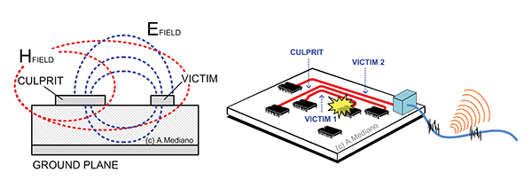
Crosstalk is especially dangerous when routing critical signals in emissions close to critical signals in susceptibility (Figure 1).

As shown in Figure 1 (left), coupling can be created by electric field lines (E) or magnetic field lines (H) going from culprit to victim circuits.
Electric field coupling is usually a problem related with high impedance victims and high dV/dt culprits. Magnetic with low impedance v field coupling is usually a problem related victims and high dI/dt culprits.
The coupling can create internal and external problems. For example, in Figure 1 right, a CULPRIT signal can affect an internal circuit VICTIM 1, or can corrupt a trace connected to I/O cables (VICTIM 2) creating failures in radiated emissions.
Typical culprit signals are high frequency (RF) or small rise/fall time signals (digital or power signals in switching topologies).
Typical victim signals are low amplitude signals (i.e. receivers in communications), high impedance signals (resets, crystal areas in clocks, operational amplifier input lines, etc.), and low impedance signals with big loops.
To minimize this effect, it is typically recommended to keep culprits as far as possible from victims. That is because the partitioning phase of your design process is so important.
This month we will see an example of a crosstalk problem between lines routed in parallel in a PCB (Figure 2).
A digital clock is applied to connector K1 using the micro-switch SW1 with six positions. The clock is redirected to TRACE 4 terminated in R4 (50ohms). All other positions in switch are OFF.
With that layout, we can see crosstalk between the PCB traces (do not forget that an additional crosstalk appears in the internal structure of the micro-switch).
The PCB is shown in Figure 3 where traces in red color are located in top layer and the return path for all signals is in bottom layer in blue color.
With the system ON, we measure the activity below the PCB (Figure 4) identifying clearly the harmonics associated to the 20MHz clock signal and some residual activity in the 88-108MHz band from nearby FM transmitters (close to my laboratory).
Note from the spatial scan how clearly is identified the loop for current of the clock using TRACE 4 as forward path and the return path in the GND trace (bottom layer).
The coupling from the clock signal internally in the switch (basically capacitive) and externally in the PCB (loops in the layout) corrupt the other theoretically non-active signals with energy from that clock. We can see an example in Figure 5.
My final advice: Aggressive signals close to sensitive signals in connectors or parallel traces can be coupled. Capacitive coupling is typical for high impedance victims. Inductive coupling is related with low impedances and big loops. Try to separate those kind of signals to minimize EMI in your products.