Associate Professor Neils Jonassen authored a bi-monthly static column that appeared in Compliance Engineering Magazine. The series explored charging, ionization, explosions, and other ESD related topics. The ESD Association, working with In Compliance Magazine is re-publishing this series as the articles offer timeless insight into the field of electrostatics.
Professor Jonassen was a member of the ESD Association from 1983-2006. He received the ESD Association Outstanding Contribution Award in 1989 and authored technical papers, books and technical reports. He is remembered for his contributions to the understanding of Electrostatic control, and in his memory we reprise “Mr. Static”.
~ The ESD Association
Reprinted with permission from: Compliance Engineering Magazine, Mr. Static Column Copyright © UBM Cannon
In a previous article we discussed the phenomenon of induction, that is, the effect of an electric field on a conductor (see Mr. Static in the September 2011 issue). If a conductor is placed in an electric field, charges will move within the conductor until the interior field is zero. If the conductor is grounded, the free induced charge disappears. If the ground connection is broken and the conductor is removed from the field, the conductor will retain a net charge. It has been charged by induction.
Now suppose that the material placed in the electric field is an insulator. This being the case, the above processes cannot take place because of the absence of mobile charge carriers. But the field may disturb the otherwise symmetrical distribution of positive and negative charges in the molecular structure of the insulator. Where this slight relative shift of electrons and nuclei is created in an electric field we have an effect called polarization.
But before we begin explaining what polarization is, we should touch briefly upon what it means to compliance engineers and other electronics industry professionals. And its meaning is twofold. For polarization can be not only beneficial, making it possible to increase the capacitance of capacitors, but also detrimental, causing plateout to occur on all types of surfaces in an electric field, for instance on wafers in cleanrooms.
Examples
Figure 1 shows an atom in a field-free region. The time-mean distribution of the atom’s charges is symmetrical, so that there is no external field. The atom is neutral. If an electric field E is applied (Figure 2), the symmetry will be disturbed. The electrons, or rather the center of distribution of the electrons, will be displaced in the opposite direction of the field. For some materials, the nucleus may shift its position in the direction of the field.
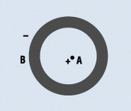
Figure 1: Atom in field-free region with nucleus (A) and symmetrical electron cloud (B).

Figure 2: Atom in electric field (E) with nucleus (A) and asymmetrical electron cloud (B).
The situation shown in Figure 2 may be represented by a negative charge and a positive charge separated by a distance dependent on the field strength Figure 3). This is called an electrical dipole, and such dipoles are formed throughout the insulator, hence the name polarization.
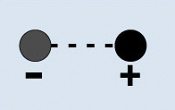
Figure 3: Electrical dipole.
An insulator in which dipoles may be formed is often called a dielectric. The dipoles line up end to end along the field lines. If the field is rectilinear, we can imagine a situation like the one shown in Figure 4. The internal positive and negative charges cancel each other, and the dipole string acts like one long dipole (Figure 5). So what will these polarization dipoles do to the field inside the dielectric? Let’s answer this question in two steps.

Figure 4: Dipole string.
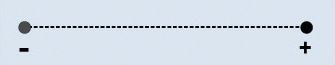
Figure 5: Simplified dipole string.
A conductor “A” placed in an electric field with the strength E0 is shown in Figure 6. The field binds (in this case) a negative charge on the left side (i.e., the bound induced charge) and frees an equally large positive charge on the right side (i.e., the free induced charge). Thus, the total field inside the conductor is zero. The free charge may be removed if the conductor is grounded. (An explanation of this situation was given in the article on induction in the September 2011 issue).

Figure 6: Conductor in electric field (induction).
If, however, the body A is a dielectric, the situation is different (see Figure 7). The external field E0 causes polarization, that is, it forms dipole strings. These strings will be stacked on top of each other, creating a dipole field Ep in the opposite direction of and superimposed on E0.
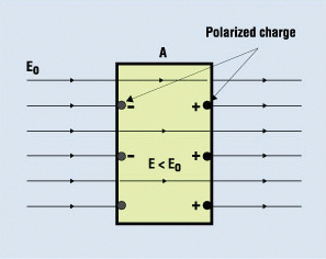
Figure 7: Dielectric in electric field (polarization).
The resulting field
E = E0 – Ep
is smaller than E0, and it turns out that
![]()
is a constant characteristic for the dielectric in question. The value εr is called the relative permittivity or dielectric constant. Many commonly used dielectrics have εr values from 2 to 7. The charges of the dipoles are called polarized charges. In contrast to induced charges, polarized charges cannot be removed from the dielectric. The situation shown in Figure 7 is the simplest possible, with the external field being homogeneous and the field lines being perpendicular to the sides of the dielectric. If the field lines are not perpendicular to the sides of the dielectric, E0 and E will not be parallel. In such a case, a “refraction” happens at the interface, and we have a parallel to Snell’s law of optical refraction, where the optical refractive indices are substituted by the relative permittivities.
Let’s consider two practical effects of polarization.
Effect on Capacitance. Figure 8a shows a parallel-plate capacitor connected to an electrometer. The assumption is that the capacitance of the electrometer is negligible compared with that of the parallel-plate capacitor. There is air (or vacuum) between the capacitor plates. The system is charged with a charge q, and a voltage Vv is displayed on the electrometer. When the space between the capacitor plates is filled with a dielectric (Figure 8b) the voltage drops to Vd. As previously explained, the field strength in the dielectric will be εr times smaller than it was in air, and because the voltage difference across the capacitor is the field strength times the plate spacing, s, we have the following:
![]()
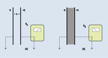
Figure 8: A parallel-plate capacitor connected to an electrometer.
And, since the charge q is the same in the two situations,
Cd = εr • Cv.
The capacitance thus increased by the factor εr when the interspace was filled by the dielectric. Using a dielectric in a capacitor has another advantage—an increase in the breakdown voltage. This occurs because the breakdown field strength of a dielectric is usually considerably higher than that of air.
Polarization Plateout. Figure 9 shows an airborne, insulative (dielectric) particle P in an inhomogeneous field E. The field polarizes the particle.

Figure 9: Polarization plateout.
The positive and negative polarized charges have the same numerical value, but because the field strength is higher at the positive end than at the negative one, the positive force F+ will be stronger than the negative force F–.
The result is a net force
F = F+ – F–
in the direction of increasing field strength. The uncharged particle tends to move in an inhomogeneous field and eventually lands or plates out on the first solid or liquid surface intersecting the field lines. (It should be noted that if the particle P is conductive, induction will make it behave in a similar way.)
Suppose we have a positively charged surface, for instance, a sheet of plastic. The sheet will obviously attract negatively charged, airborne particles and reject the positive ones, but what may be just as relevant is that it definitely will also make the neutral particles move, not necessarily toward the charged surface, but always in the direction of increasing field strength. An important example of this is the occurrence of static charges in cleanrooms. Although the air is clean, there are always some airborne particles around. For example, if a wafer carrier has a charge, it may cause, by polarization plateout, some of the particles to land on the wafer surface with very unwanted results, at worst a ruined wafer.
Let’s finish this by looking at another well-known example of polarization plateout—the field in front of a monitor or TV screen. The field (created by the electrodes in the tube) is strongest at the surface of the screen, so the particles plate out there.
Now if a viewer faces the front of the screen, he or she will be virtually at ground potential, so the field lines will converge toward his or her face, especially around the nose and chin, and possibly around the ears. These areas are now the primary sites of plateout. It has been demonstrated that the plateout rate of airborne particles to the viewer’s face is much higher in the situation just discussed than when the viewer is in a field-free region. It has also been suggested that this effect could be the cause of skin diseases and other ailments contracted in the presence of airborne allergens. This claim, however, does not seem to have been scientifically proven.
Conclusion
The purpose of this article has been to give an idea of some of the basic features of the phenomenon of polarization. It should be stressed, however, that the presentation is far from complete. A thorough treatment would have resulted in a much longer paper with an exercise in atomic physics and higher mathematics that probably would have scared some readers away. ![]()
|
|
Niels Jonassen, MSc, DSc |