
In this article, we compare the shielding effectiveness of various solid metallic shields by direct H-field measurements in the near field of the source. We also show the detrimental effect of the shield apertures on the shielding effectiveness. The source of the H field is a step-down (buck) SMPS operating at a fundamental frequency of 118 kHz. The shields evaluated are: phosphor-bronze, nickel-silver, and cold-rolled steel. The measurements are taken 5 mm from the source of the field in the frequency range of 100 kHz to 1 MHz. The shields’ thickness is either 8 or 15 mils, and thus the shields are considered to be thick in the range of the frequency of interest.
Foundations
In the near-field, the reflection loss depends on the type of the source. The reflection loss for the near-field magnetic sources is [1], [2]:
 (1)
or equivalently,
 (2)
The absorption loss is given by
 (3)
or equivalently,
 (4)
In Equations 1-4, f is the frequency in Hz, r is the distance in meters, t represents the thickness of the shield in inches, and µr, and σr, are the relative permeability (with respect to free space) and relative conductivity (with respect to copper), respectively.
The total shielding effectiveness is the sum of the reflection and absorption losses
 (5)
Verification
To validate the theoretical formulas of the previous section, we used a step-down SMPS [3] operating at a fundamental frequency of 118 kHz, and performed H-field probe measurements with the probe placed directly above the source as shown in Figure 1 [4].

The shields evaluated in this article are described in Table 1.
| Material | Thickness (inches) |
Relative Permeability, µr | Relative Conductivity, σr |
| Phosphor Bronze | 0.008 | 1 | 0.15 |
| Phosphor Bronze | 0.015 | 1 |
0.15 |
|
Nickel Silver |
0.008 |
1 | 0.058 |
| Cold-Rolled Steel | 0.015 | 100 | 0.106 |
Table 1: Shield configurations
First, we compared the phosphor-bronze shields with thicknesses of 8 mils and 15 mils. The measurement results are shown in Figure 2.

Since the shields are made of the same material, the reflection losses for both shields are the same. The absorption loss depends on the shield thickness, and thus, the absorption loss for the 15 mil shield is larger than that for the 8 mil shield. It follows that the total shielding effectiveness for the 15 mil shield is larger than that for the 8 mil shield. Figure 2 confirms these conclusions. It should be noted that Figure 2 shows the H-field measurements (and not the shielding effectiveness); these near-field measurements, however, follow the trend specified by the theoretical equations of the previous section.
Next, let’s compare phosphor-bronze and nickel-silver shields, both 8 mil thick. The measurement results for these shields are shown in Figure 3.

Both shields have the same thickness, same permeability, but different conductivities. The conductivity of the phosphor-bronze is higher than that of nickel silver. Therefore, its reflection and absorption losses are also higher; so is the total shielding effectiveness. This is confirmed in Figure 3.
Now, let’s compare phosphor-bronze and cold-rolled steel shields, both 15 mils thick. The measurement results for these shields are shown in Figure 4.

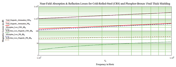
The measurement results clearly show that the cold-rolled steel shield dramatically outperforms the phosphor-bronze shield, especially above 500 kHz. The explanation for why this happens is a bit more involved, since the shields have different permeabilities and different conductivities.
Evaluating the expression in Equation (2) for phosphor-bronze, we get
 (6)
While for cold-rolled steel we obtain
 (7)
Thus, the reflection loss for phosphor-bronze is about 21.5 dB higher than that for cold-rolled steel, at all frequencies.
Now, let’s look at the absorption loss. Evaluating the expression in Equation 4 for phosphor-bronze, we get
 (8)
While for the cold-rolled steel we have
 (9)
Thus, the absorption loss for cold-rolled steel is about 8.36 times that of the phosphor-bronze. Note that this difference increases with frequency. Thus, as the frequency increases, the total loss, i.e., the total shielding effectiveness of the cold-rolled steel becomes higher.
At 100 kHz, the absorption loss of the cold-rolled steel is about 15 dB higher than that of the phosphor-bronze. At 500 kHz, the difference is almost 38 dB. This explains why the cold-rolled steel outperforms phosphor-bronze, especially at higher frequencies. Simulation results in Figures 5 and 6 agree with the H-field measurement trends shown in Figure 4.

Finally, we show the detrimental effect of the shield apertures on the shielding effectiveness. Figure 7 shows the 15-mil-thick cold-rolled steel solid shield, as well as a shield with apertures (holes) in it.

H-field measurement results for these shields are shown in Figure 8.

It is apparent from the measurement results shown in Figure 8 that the presence of apertures reduces the shielding effectiveness of a solid shield.
References
- Clayton R. Paul, Introduction to Electromagnetic Compatibility, Wiley, 2006.
- Henry W. Ott, Electromagnetic Compatibility Engineering, Wiley, 2009.
- Bill Spence, Shielding Tutorial – Lunch and Learn, Gentex Corp, 2013.
- Bogdan Adamczyk, Foundations of Electromagnetic Compatibility with Practical Applications, Wiley, 2017.
