
Ferrites for EMI suppression are usually chosen looking for high (resistive) impedance at the frequency of interest; but, sometimes, that ferrite is not working as expected. Perhaps you have saturation effects?
Many EMC radiated emission problems from electronic products can be solved with the insertion of a ferrite in the EMI signal path.
In that way, losses at the frequencies of interest are introduced in common or differential modes with good results especially if terminal impedances are low at those frequencies.
Some months ago I was involved in a design problem in a company where two small SMD ferrites had been used to reduce emissions in the VHF range. The product was a small lighting equipment injecting EMI in LINE and NEUTRAL.
To reduce EMI, two ferrites F had been included in both paths as shown in Figure 1.

The impedance of ferrites was intended to introduce insertion losses in the system with terminal impedances Zmains and Zout. Note that, for EMI analysis purposes, the circuit is the signal source with Zout output impedance and Zmains (unknown) is load impedance.
In first prototype, WE-CBF SMD EMI Suppression ferrite beads from Würth Elektronik with reference 74279244 were selected with success. Those ferrites will be referenced as option F1 in this article.
In a new version of the design the ferrites were replaced with “equivalents”: same manufacturer, similar package, similar current specifications, and MORE impedance at the frequency of interest. The new option will be referenced here as F2, and the manufacturer’s code for the new ferrite was 742792141.
From Figure 2 note that both ferrites have similar characteristics even F2 option looks more effective at 100MHz because the difference in impedance value.

The experimental results were a surprise for the company: CM emissions in the 100MHz range were 8-10dB higher with the second option (Figure 3).

Ferrites F2 are inserting (in theory) more impedance. Ferrites are adequate for the frequency range. Size and package of ferrites are similar. Terminal impedances are equivalent for both cases. Where is the difference?
If you find this effect in your system, think about saturation. If DC or low frequency current (e.g. 50-60Hz) is going through the component, the nominal impedance at EMI frequency can be reduced from the nominal values in datasheet without that DC/LF “bias”.
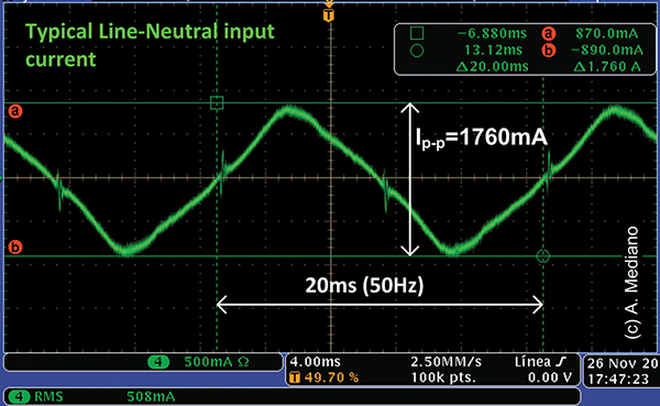
To check for that condition, the input current of the product was measured in both LINE and NEUTRAL wires and approximately 870-890mA peak current (508mArms) was measured in the experiment (Figure 4).
In the datasheet, the “rated current” value is included as you can see in Figure 2 but that current is specified as information referring to 40K self-heating.
The effect of saturation was evaluated using a simple simulation with SPICE models of the components available in the website of the manufacturer (this is very useful information for the design process).
In Figure 5 the impedances of the ferrites versus frequency with DC current is included from a simulation using LTSPICE.

Note the reduction in impedance at 100MHz is more important for F2 and impedance changes in both ferrites from partially reactive and resistive without DC to purely reactive (inductive) with DC levels.
A new simulation was prepared to evaluate the insertion losses of the ferrites with 10 ohms terminal impedances (Figure 6).

Without DC, insertion losses at 100MHz are better with option F2 as predicted with information in Figure 2 (more impedance at that frequency).
With DC bias and because saturation effects, ferrite F2 is not the optimum selection (-14dB versus -21dB for option F1). The difference can be related with the experimental results obtained in Figure 3.
So, when considering ferrites to reduce EMI emissions, do not forget to check saturation effects in your application: DC or low frequencies are important for the RF behavior.

 Arturo Mediano received his M.Sc. (1990) and his Ph. D. (1997) in Electrical Engineering from University of Zaragoza (Spain), where he has held a teaching professorship in EMI/EMC/RF/SI from 1992. From 1990, he has been involved in R&D projects in EMI/EMC/SI/RF fields for communications, industry and scientific/medical applications with a solid experience in training, consultancy and troubleshooting for companies in Spain, USA, Switzerland, France, UK, Italy, Belgium, Germany and The Netherlands. He is the founder of The HF-Magic Lab®, a specialized laboratory for design, diagnostic, troubleshooting, and training in the EMI/EMC/SI and RF fields!, and from 2011, he is instructor for Besser Associates (CA, USA) offering public and on site courses in EMI/EMC/SI/RF subjects through the USA, especially in Silicon Valley/San Francisco Bay Area. He is Senior Member of the IEEE, active member from 1999 (now Chair) of the MTT-17 (HF/VHF/UHF) Technical Committee of the Microwave Theory and Techniques Society and member of the Electromagnetic Compatibility Society. Arturo can be reached at a.mediano@ieee.org. Web: www.cartoontronics.com.