This article discusses the impact of a shunt inductive discontinuity along the line as well as the effect of feeding two transmission lines in parallel. The analytical results are verified through the HyperLynx simulations and laboratory measurements.
1.1 Reflections at the Shunt Inductive Discontinuity – Analysis
Consider the circuit shown in Figure 1.1, where the transmission line of length l has a shunt inductive discontinuity in the middle of the line at a location z = d.
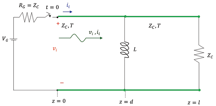
Note that the transmission line is matched at the source and at the load; it is also assumed that the initial current through the inductor is zero, iL (0– = 0).
When the switch closes at t = 0, a wave originates at z = 0, [1], with
![]() (1.1a)
(1.1a)
![]() (1.1b)
(1.1b)
and travels towards the discontinuity. When this wave arrives at the discontinuity (at the time t = T), the reflected waves, vr and ir are created. The transmission line immediately to the right of the discontinuity looks to the circuit on the left of the discontinuity like a shunt resistance equal to the characteristic impedance of the right line [2]. Figure 1.2 illustrates this.
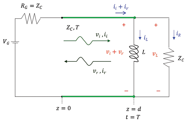
The reflected current wave is related to the reflected voltage wave by
![]() (1.1c)
(1.1c)
KVL and KCL at the discontinuity produce
![]() (1.2a)
(1.2a)
![]() (1.2b)
(1.2b)
Our initial goal is to determine the reflected voltage vr (t) at the location z = d, i.e., vr (d, t). The ultimate goal is to determine the total voltage at the discontinuity, vL (d, t).
The current iR (t) can be expressed as
![]() (1.3)
(1.3)
From Eq. (1.2b), we obtain the inductor current as
![]() (1.4)
(1.4)
Utilizing Equations (1.1b), (1.1c), and (1.3) in (1.4) we get
![]() (1.5)
(1.5)
The differential v-i relationship for the inductor is
![]() (1.6)
(1.6)
Using Equations (1.1a), (1.2a), and (1.5) in Eq. (1.6) we obtain
![]() (1.7)
(1.7)
or
![]() (1.8)
(1.8)
This differential equation needs to be solved for vr (t), for t > T, subject to the initial condition vr (t = T). Let’s determine this initial condition. Initially, the current through an inductor iL (T–) is zero. Thus, the inductor acts as an open circuit, and the incident wave sees the discontinuity as a matched load. Therefore, there is no reflection and
![]() (1.9)
(1.9)
Eq. (1.8) can be written as
![]() (1.10)
(1.10)
where
![]() (1.11)
(1.11)
The solution of Eq. (1.10) was derived in [2] as
![]() (1.12)
(1.12)
Utilizing Equations (1.9) and (1.11) in Eq. (1.12), we obtain
 (1.13)
The total voltage across the discontinuity is
![]() (1.14a)
(1.14a)
or
 (1.14b)
Equation (1.14b) predicts that at t = T, the voltage at the load rises from zero to VG/2 and then decays exponentially to z. Let’s verify these observations through simulations and measurements.
1.2 Reflections at the Inductive Discontinuity – Simulation
Figure 1.3 shows the HyperLynx schematic of the transmission line with an inductive discontinuity.
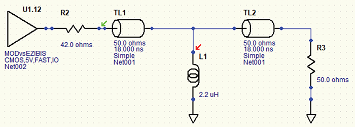
The simulation results are shown in Figure 1.4.

Note that the simulation results verify the analytical results.
1.3 Reflections at the Inductive Discontinuity – Measurements
The measurement setup is shown in Figure 1.5.
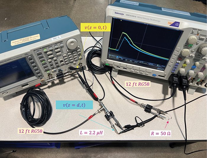
The measurement results are shown in Figure 1.6.
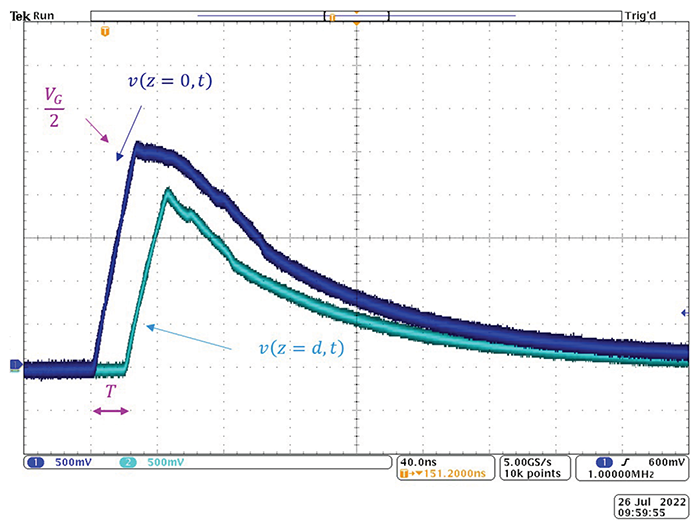
Note that the measurement results verify the simulation and analytical results.
2.1 Feeding Transmission Lines in Parallel – Analysis
Consider the circuit shown in Figure 2.1, where the transmission line of length d is connected to the two other transmission lines.
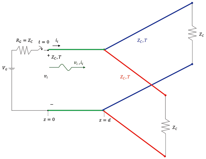
Note that load resistors are matched to the transmission lines, and all transmission lines have the same characteristic impedances. This makes the simulations and measurements easier to follow since there are no reflections at the loads.
When the switch closes at t = 0, a wave originates at z = 0 and travels towards the discontinuity. The transmission lines immediately to the right of the discontinuity look to the circuit on the left of the discontinuity like two resistances in parallel. Their values are equal to the corresponding values of their characteristic impedances. When the incident wave arrives at the discontinuity (at the time t = T), the reflected wave, vr and ir, is created, and we have a situation depicted in Figure 2.2.
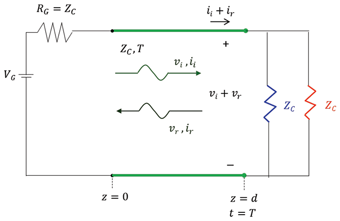
This part of the circuit is identical to the one discussed in [3] where the transmission line had a shunt resistive discontinuity. Thus, the total voltage across at the discontinuity is
![]() (2.1)
(2.1)
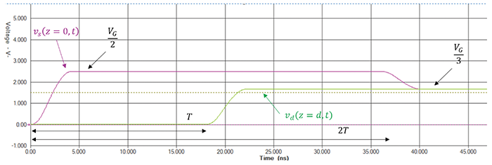
and the total voltage at the source (after t = 2T) is
![]() (2.2)
(2.2)
2.2 Feeding Transmission Lines in Parallel – Simulations
Figure 2.3 shows the HyperLynx schematic of the transmission line in parallel.
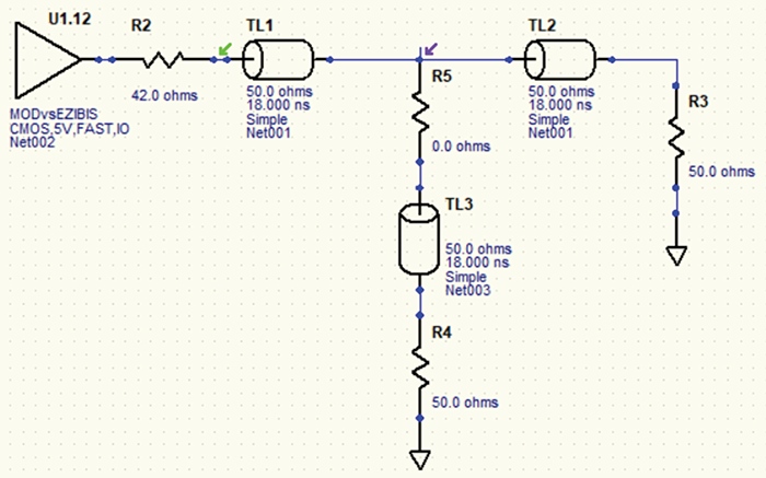
The simulation results are shown in Figure 2.4.
2.3 Feeding Transmission Lines in Parallel – Measurements
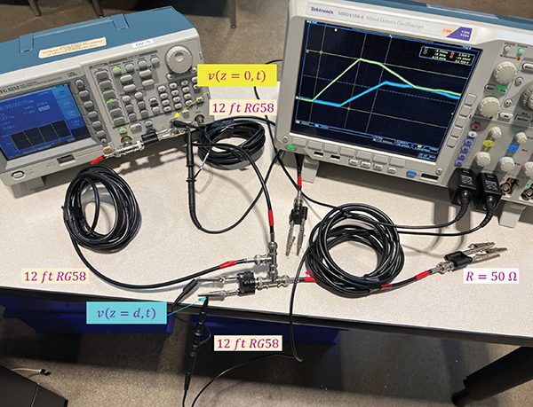
The measurement setup is shown in Figure 2.5.
The measurement results are shown in Figure 2.6.
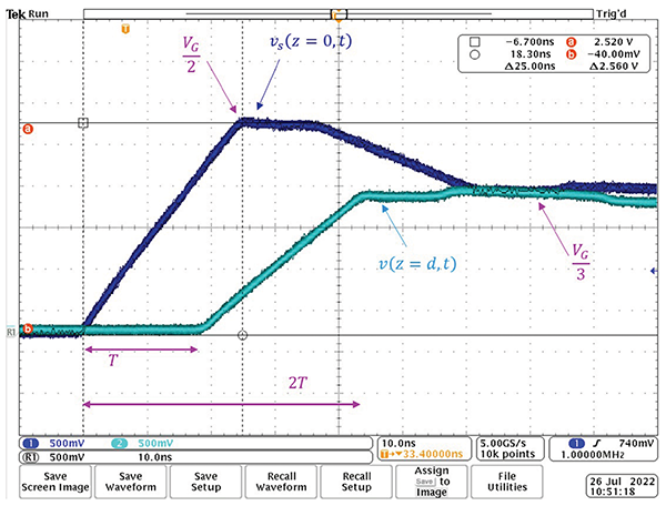
Note that the measurement results verify the simulation and analytical results.
References
- Adamczyk, B., “Transmission Line Reflections at a Resistive Load,” In Compliance Magazine, January 2017.
- Adamczyk, B., Foundations of Electromagnetic Compatibility with Practical Applications, Wiley, 2017.
- Adamczyk, B., “Transmission Line Reflections at a Shunt Resistive and Reactive Discontinuity Along the Line,” In Compliance Magazine, October 2022.
