
Usually HF filters are designed using inductors with cores. In this way a medium/high inductance value is obtained in small size components. But using cores has a limitation: the core can be saturated by DC or low frequency currents. And, sometimes not only currents can saturate the cores.
I will explain a situation I suffered some years ago while troubleshooting an audio product with EMI problems: two speakers to be installed in ceiling with typical application at home, hotels, offices, etc. (Figure 1).
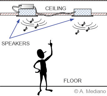
The audio product was composed by two speakers and one electronic unit containing a 20W class D power amplifier.
The design was working in in the lab but, when installed in the final location (ceiling), the output was plenty of noise. Mystery?
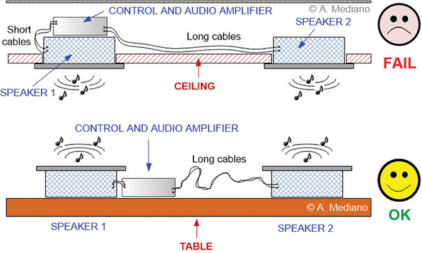
While trying to understand the reason for the failure I detected a 2” small difference: in the final installation the electronic unit was installed on top of one of the speakers, but in the lab, the electronic unit was on top of a table, far from top area of the speaker (Figure 2).
To explain the reason for that difference, I built a prototype.
First, you need to know that class D amplifiers are switching amplifiers, and switching amplifiers are noisy and EMI generators. Typically they are a source for radiated EMI in the HF/VHF bands, especially if long cables are used from amplifier to speaker.
The EMI signals are usually reduced with some kind of low pass filter working in common and differential modes.
For our product, a Texas Instruments TPA3001 monaural class D power amplifier was used. The amplifier was included in a small PCB referred as PCB#1 in Figure 3.
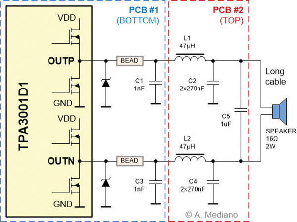
The filter low pass filter was built around C1-L1-C2, C3-L2-C4 and C5. Additionally, two ferrite beads Fair−rite 2512067007Y3 (0.05Ω DCR, 70Ω @100MHz, 3A) were included to help passing FCC/CE regulations in frequencies greater than 30MHz.
L1 and L2 were two 47uH inductors TOKO 822LY-470K (0.17Ω DCR, SRF 6.5MHz, 1.4A)
As shown in Figure 3, part of the low pass filter was included in a second PCB (PCB#2 in Figure 3).
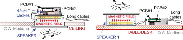
And here is the subtle difference: in the final installation both L1 and L2 chokes are placed near to the speaker, where a high magnetic field is present. See Figure 4 (left) to understand how the inductors receive magnetic field lines from the speaker. In Figure 4 (right), the electronic unit is on top of the table and the magnetic field lines do not arrive to the inductors.
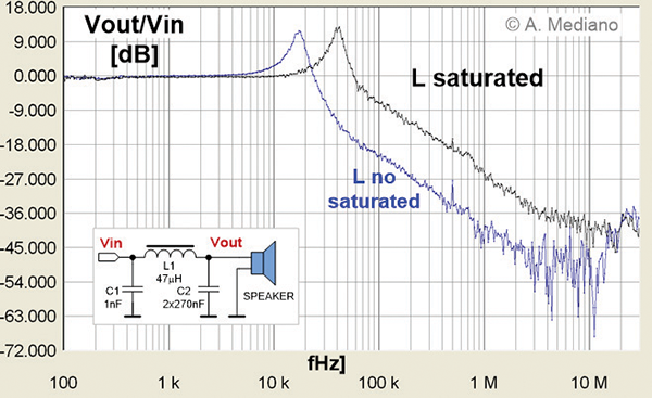
The inductance of the coils was measured with and without the magnetic field excitation. The inductance changed from 47uH (nominal value without external DC magnetic field) to 7uH while on top of the speaker. This is a similar situation to saturation because DC or low frequency current through the inductor.
The response of the filter was measured and results appear in Figure 5. The ratio Vout/Vin was measured with and without the speaker on top of the inductors. Around 12dB higher is the response of the filter in the 250kHz-10MHz range for the saturated case (note the dangerous underdamping response of the filter).
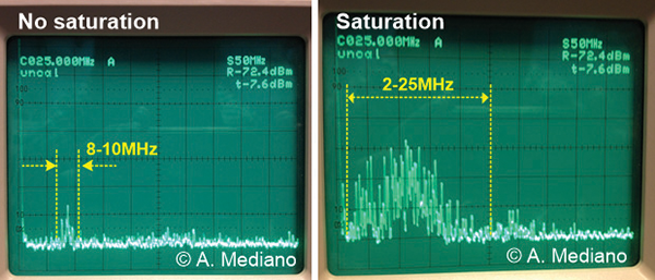
Finally, the common mode current in speaker cable was measured in the 1MHz-50MHz range when 1kHz tone was applied to the input of the amplifier (Figure 6). Note the difference in the HF range of the spectrum.
My final advice: when designing EMI filters with inductors, special attention is required to core saturation not only from DC or low frequency currents but external magnetic fields from speakers, transformers, and other unexpected sources. Toroidal cores or separation from those sources are common solutions.
 Arturo Mediano received his M.Sc. (1990) and his Ph. D. (1997) in Electrical Engineering from University of Zaragoza (Spain), where he has held a teaching professorship in EMI/EMC/RF/SI from 1992. From 1990, he has been involved in R&D projects in EMI/EMC/SI/RF fields for communications, industry and scientific/medical applications with a solid experience in training, consultancy and troubleshooting for companies in Spain, USA, Switzerland, France, UK, Italy, Belgium, Germany, Canada, The Netherlands, Portugal, and Singapore. He is the founder of The HF-Magic Lab®, a specialized laboratory for design, diagnostic, troubleshooting, and training in the EMI/EMC/SI and RF fields at I3A (University of Zaragoza), and from 2011, he is instructor for Besser Associates (CA, USA) offering public and on site courses in EMI/EMC/SI/RF subjects through the USA, especially in Silicon Valley/San Francisco Bay Area. He is Senior Member of the IEEE, active member from 1999 (Chair 2013-2016) of the MTT-17 (HF/VHF/UHF) Technical Committee of the Microwave Theory and Techniques Society and member of the Electromagnetic Compatibility Society. Arturo can be reached at a.mediano@ieee.org. Web: www.cartoontronics.com.