In this article we investigate the frequency behavior of a ceramic capacitor. The frequency responses of the capacitor are studied for three different cases: a) no connecting traces, b) short connecting traces, c) long connecting traces. Theoretical models are validated by the simulations and measurement results.
Foundations
Understanding the non-ideal behavior of a capacitor is essential in EMC. Realistic capacitors exhibit non-ideal effects that can be modeled by augmenting the ideal model with parasitics [1]. From the EMC standpoint, the most important parasitic is the lead inductance associated with the connecting traces. We will, therefore, focus on the impact of the connecting trace length on the frequency behavior.
We begin by presenting circuit models and the impedance vs. frequency curves for an ideal and non-ideal capacitor, shown in Figure 1.
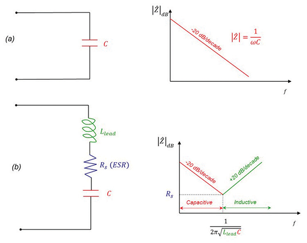
In the case of an ideal capacitor, the magnitude of its impedance decreases linearly with frequency, at a rate of 20 dB/decade. In the case of a non-ideal capacitor, the magnitude of its impedance decreases linearly at a rate of 20 dB/decade, up to the resonant frequency, beyond which it increases at a rate of 20 dB/decade. The model shown in Figure 1b is valid up to a few hundred megahertz. The curves drawn are straight-line Bode plot approximations.
Figure 2 shows a simulation model and the impedance results for a 120-pF capacitor corresponding to the three lead length cases.
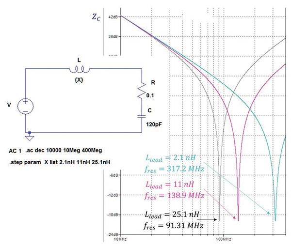
The response curve on the left corresponds to the capacitor with no connecting leads, and its parasitic inductance of 2.1 nH. The middle curve shows the results for the lead inductance, Llead, of 11 nH (short trace) while the far right curve corresponds to the lead inductance of 25.1 nH (long trace). Note that increasing the lead inductance shifts the resonant frequency to the left; from 317.2 MHz for no trace, to 138.9 MHz for a short trace, and 91.31Mhz for a long trace. This is consistent with analytical formula for the resonant frequency
 (1)
(1)
These results are verified next, in the measurement section.
Verification
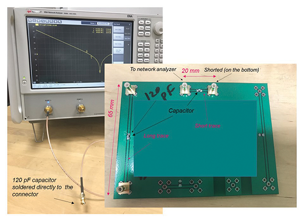
The experimental setup and the board used for impedance measurements [2], are shown in Figure 3.
Impedance measurement (s11 measurement) result for the no-connecting-traces case is shown in Figure 4.
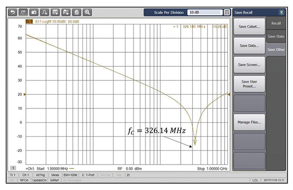
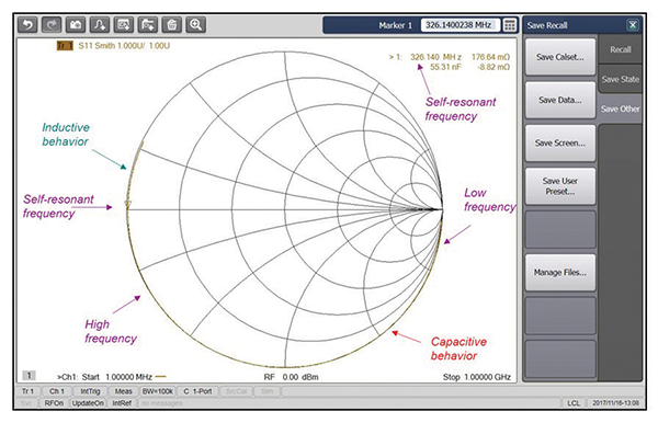
The impedance decreases with frequency (capacitive behavior) up to the self-resonant frequency, beyond which it increases with frequency (inductive behavior). Note the relatively high value of the self-resonant frequency (326.14 MHz). This value is consistent with the simulated value of 317.2 MHz, corresponding to the lowest lead inductance of 2.1 nH.
Figure 5 shows the Smith Chart plot of the impedance. The impedance starts out being capacitive (lower half-circle of Smith Chart); as the frequency increases the resonant point is reached and the impedance becomes inductive (part of the circle in the upper plane).
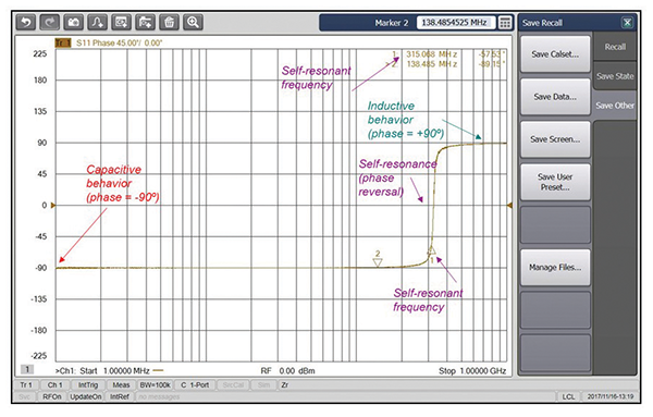
The phase plot of the capacitor impedance is shown in Figure 6. Note that the phase of the impedance is -90º (capacitive behavior) up to the self-resonant frequency, where the phase reversal occurs. Beyond that frequency the phase is inductive and equal +90º.
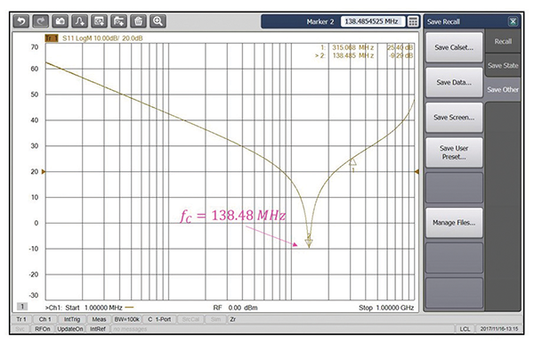
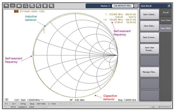
The impedance, Smith Chart, and phase plots for the short-trace case are shown in Figures 7-9. Note the dramatic shift in the self-resonant frequency from 315 MHz to 138.5 MHz.
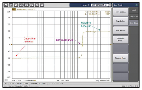
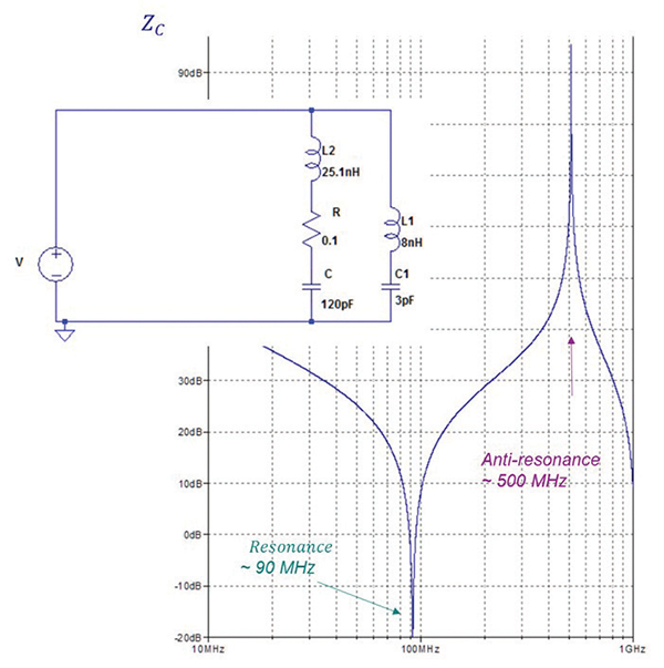
The impedance, Smith Chart, and phase plots for the long-trace case are shown in Figures 10-12. Note that the self-resonant frequency is further reduced from 138.5 MHz to 89.6 MHz. This value is consistent with the simulated value of 91.3 MHz, corresponding to the high lead inductance of 25.1 nH.
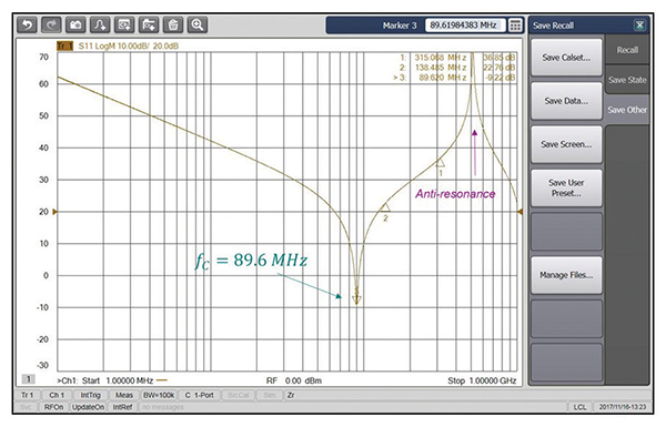
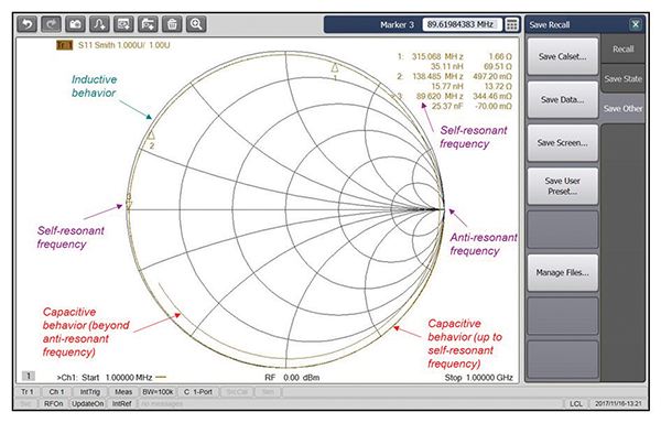
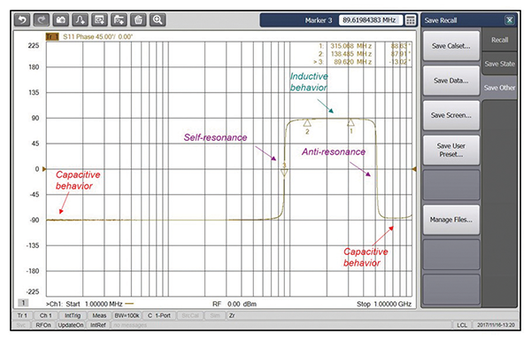
Also note the antiresonant point beyond the self-resonant frequency. This behavior was not present in the simulation model in Figure 2. Why? Because our simulation model was relatively simple and included just one capacitance and one inductance. The more accurate, high-frequency model for the long-trace case is shown in Figure 13. The original model of Figure 2. is augmented by an LC configuration (8 nH inductance and 3 pF capacitance) representing the parasitic inductance and capacitance of the long trace and the ground plane. Note that this model accurately predicts the resonant and antiresonant peaks and frequencies.
The measurement results verify the analysis presented in the previous section. As the component trace length is increased the parasitic loop inductance is increased. This increased inductance decreases the self-resonant frequency of the capacitor. This is particularly troublesome when capacitors are used for decoupling purposes where they’re supposed to provide a low-impedance path for the high-frequency currents during switching.
References
- Bogdan Adamczyk, Foundations of Electromagnetic Compatibility with Practical Applications, Wiley, 2017.
- Bill Spence and Pete Vander Wel, Designers of the PCB used for Impedance Measurements, Gentex Corp, 2008.
