
When garments are specified as part of an ESD control program, they must be qualified and verified by testing. There are established test method standards, including ANSI/ESD STM 2.1 [1], IEC 613404-9 [2], etc., for measuring various resistance parameters. There are, however, some fabrics for which resistance measurements are not appropriate, and so alternative test methods are required.
What are the different types of garments?
IEC 61340-4-9, which is derived from ANSI/ESD STM 2.1 and ANSI/ESD S1.1 [3], specifies three different types of garments:
- static control garments, which are personnel garments designed for electrostatic charge control;
- groundable static control garments, which exhibit electrical resistance from point-to-point and from any point or panel on the garments to the groundable point on the garments;
- groundable static control garment systems, which are garments used to establish the primary ground path for persons to the groundable points of the garments and the connection of the garments to ground, typically through grounding cords.
IEC 61340-4-9 specifies resistance measurements and recommends resistance limits. Required resistance limits are specified in IEC 61340-5-1 [4] and ANSI/ESD S20.20 [5]. These limits are shown in Table 1.
| Type of Garment | Parameter | Resistance Limits |
| Static control garments | Resistance point-to-point | < 1.0 x 10¹¹ Ω |
| Groundable static control garments | Resistance point-to-point and resistance to groundable points | < 1.0 x 10⁹ Ω |
| Groundable static control garment systems | Resistance point-to-point and resistance to groundable points | < 1.0 x 10⁹ Ω |
| Total system resistance including person, garment and grounding cord | < 3.5 x 10⁷ Ω |
Table 1: IEC 61340-4-9, IEC 61340-5-1 & ANSI/ESD S20.20 resistance limits for garments.
What are the limitations of resistance measurements?
For accurate resistance measurement on garments, it is essential for measurement electrodes to make contact with conductive or dissipative components. It is common for static control garments to contain conductive or dissipative yarns or fibers incorporated into insulative base fabric. It is possible that the conductive or dissipative components are inaccessible to measurement electrodes, either because the yarns are buried within the fabric structure, or because core conductive fibers are used. Core conductive fibers typically comprise a carbon-loaded core surrounded by insulative polyester or polyamide. Because the conductive components are not accessible to the measurement electrodes, meaningful measurements are not possible. Nevertheless, garments with buried or core conductive yarns are used in many ESD control programs, and so must be qualified by alternative test methods. This is recognised in IEC 61340-5-1, which allows user defined test methods and requirements for static control garments.
What are the alternatives to resistance measurements?
IEC/TS 61340-4-2 [6] describes test methods that can be used as alternatives to resistance measurements for evaluating static control garments. In IEC/TS 61340-4-2, some of the test methods are fully developed and are specified in National and International Standards, but not necessarily for all applications for which users might require them. For example, reference is made to EN 1149-3 [7]. This test method was developed in a multi-national 2-year research program and has been validated by several inter-laboratory trials. It is a harmonised European Standard and provides a presumption of conformity to the Personal Protective Equipment (PPE) Regulation [8] for garments intended for use in explosive atmospheres. A user looking for a reliable test method might choose to use EN 1149-3 to evaluate static control garments, but might have to develop their own acceptance limits. Other test methods described in IEC/TS 61340-4-2 are well developed in terms of procedural descriptions and equipment specifications, but have not been evaluated by inter-laboratory trials appropriate for International Standards.
The alternative test methods described in IEC/TS 61340-4-2 that are appropriate for garment testing can be grouped according to measurement parameters, as summarised in Table 2.
| Measurement parameter | Standard/Technical Specification referenced |
| Charge decay time | IEC 61340-2-1 |
| EN 1149-3 | |
| NT ELEC 037 | |
| Field suppression | EN 1149-3 |
| Triboelectric charging< | IEC/TS 61340-4-2 |
Table 2: Summary of alternative test methods described in IEC/TS 61340-4-2
Charge decay time
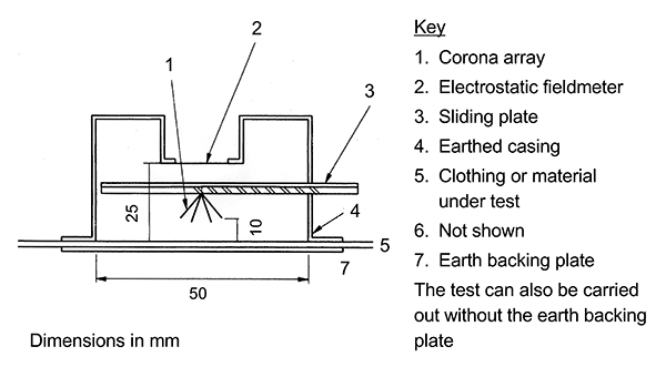
IEC 61340-2-1 [9] specifies two test methods: one using corona to charge garments, and one using a charged plate monitor (CPM) for testing gloves and finger cots. The corona charging apparatus is shown in Figure 1. A plate (3) carrying a corona array (1) is energised to deposit a patch of charge on the garment surface (5). The corona array is then removed, within 20 ms, to allow a fieldmeter (2) to record the rate at which the field strength decays.
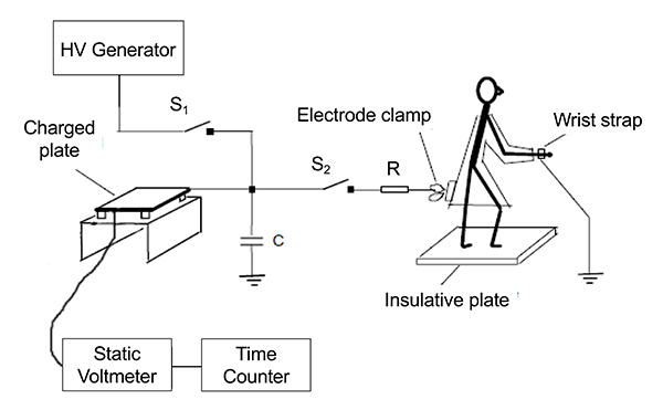
In the second test method specified in IEC 61340-2-1, a CPM is initially charged to 1100 V DC. A grounded person wearing a glove or finger cot then touches the CPM plate and the time for the voltage to fall from 1000 V to 100 V is recorded, see Figure 2.

The test method specified in NT ELEC 037 [10] is a variation of the CPM method. The test arrangement is shown in Figure 3. In this method, the CPM is discharged via a garment worn by a grounded person.
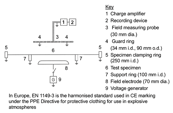
The test method specified in EN 1149-3 records the change in measured field strength resulting from charge movement within the fabric. The garment is clamped in a grounded support above an electrode that is then charged to 1200 V DC. As charge moves within conductive or dissipative components within the garment, the field strength detected by a probe above the garment will decay. The test method is used to determine two parameters: shielding and half decay time. Shielding is derived from the initial fall in recorded field strength compared to the maximum field strength when no sample is present. Half decay time is the time taken for the field strength to decay to half the maximum value. The test apparatus is shown in Figure 4.
The limits specified for EN 1149-3 for garments intended to be worn in explosive atmospheres are either shielding factor greater than 0.2, or half decay time less than 4 s. These limits were determined empirically based on correlation to ignition testing on garments and fabrics.
For static control garments, organisations should determine if the limits are appropriate for their own applications, and if not, they can develop their own limits.
Triboelectric charging
Triboelectric charging test methods have a reputation for poor repeatability and reproducibility. There are many factors that contribute to the result of any triboelectric charging test, and it is often difficult or impractical to control every one. However, lack of repeatability or reproducibility in absolute terms, does not necessarily render triboelectric charging tests unusable for qualification or compliance verification testing within an organisation. Repeatability and reproducibility of results against the organisation’s established acceptance limits are more important. With careful design and control of test conditions and apparatus, useful results can be obtained from triboelectric charging tests.
IEC/TS 61340-4-2 describes a number of different test methods. The simplest option is to rub an area of a static control garment whilst being worn and measure the field strength or surface voltage with an electrostatic fieldmeter or non-contacting voltmeter, see Figure 5.

The tribocharging device can be anything convenient that is known to generate high levels of charge on non-static control materials, e.g. Teflon® rod, woollen cloth, etc.
A more complex, laboratory level test method uses a mannequin with a defined capacitance. Parameters such as rubbing pressure, geometry of rubbing device, speed of rubbing, etc. are specified. One version of the test procedure is shown in Figure 6. In this version, charging is determined by measuring the voltage induced on the mannequin.
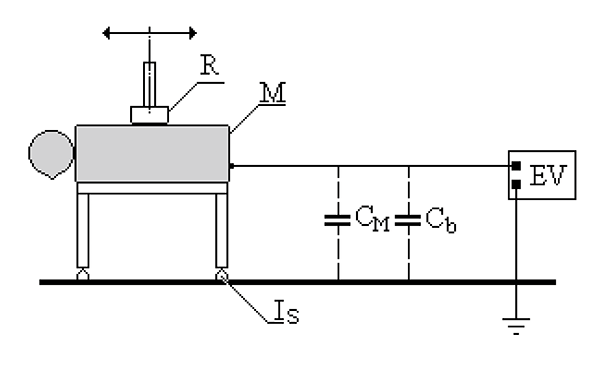
Figure 6: IEC/TS 61340-4-2 triboelectric charging test using a mannequin.
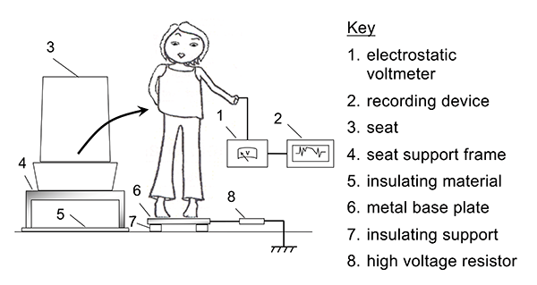
IEC/TS 61340-4-2 describes two further triboelectric charging test methods involving a person wearing a garment under test. In one test method, a person sits on a seat and then stands up. The person is connected to an electrostatic voltmeter so that the voltage induced on their body by the charge on the garment under test can be measured. The person can stand on an insulator or can be grounded either by ESD control footwear, or via a resistor to simulate ESD control footwear. The seat can be covered with different reference materials. The test arrangement is shown in Figure 7.
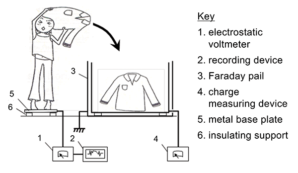
In another test method, a person stands on a metal plate connected to an electrostatic voltmeter to record body voltage. The person removes an outer garment and drops it into a Faraday pail so that the charge on the garment can be measured. In this test procedure, reference garments are used as the rubbing devices for the garment under test. The test arrangement is shown in Figure 8.
What is the best test method to use?
Guidance on selection of test methods can be taken from garment manufacturers, provided the user is satisfied that the recommended test method accurately corresponds to in-use performance within their organisation.
Another way to select a test method is by looking at requirements within the ESD control program plan. For example, there might be a requirement to keep electrostatic fields below 5 kV/m. In this case, a simple triboelectric charging test could be done, as in Figure 5, to ensure field strength from garments is below this limit. If there are surface voltage limits for insulators, a charge decay time test can be done to determine if garments are able to dissipate charge so that surface voltages falls below the maximum limit within an acceptable time.
Organisations generally want to choose test methods that are most convenient for them, using equipment and instrumentation that is already available. If the acceptance limits cannot be related to other requirements in the ESD program plan, testing to measure decay time, triboelectric charging, etc. can be done initially on garments that do meet the resistance limits for static control garments. The results for these garments can then serve as the acceptance limits for garments for which resistance measurements are not appropriate.
References
- ANSI/ESD STM 2.1 ESD Association Standard Test Method for the Protection of Electrostatic Discharge Susceptible Items – Garments – Resistive Characterization
- IEC 61340-4-9 Electrostatics – Part 4-9: Standard test methods for specific applications – Garments
- ANSI/ESD S1.1 ESD Association Standard for the Protection of Electrostatic Discharge Susceptible Items – Wrist Straps
- IEC 61340-5-1 Electrostatics – Part 5-1: Protection of electronic devices from electrostatic phenomena — General requirements
- ANSI/ESD 20.20 ESD Association Standard for the Development of an Electrostatic Discharge Control Program for Protection of Electrical and Electronic Parts, Assemblies and Equipment (Excluding Electrically Initiated Explosive Devices)
- IEC/TS 61340-4-2 Electrostatics – Part 4-2: Standard test methods for specific applications — Electrostatic properties of garments
- EN 1149-3 Protective clothing – Electrostatic properties – Part 3: Test methods for measurement of charge decay
- Regulation (EU) 2016/425 of The European Parliament and of The Council of 9 March 2016 on personal protective equipment
- IEC 61340-2-1 Electrostatics Part 2-1: Measurement methods — Ability of materials and products to dissipate static electric charge
- NT ELEC 037 Protective garments: Measurement of the charge decay time of ESD-protective garments
 Dr. Paul Holdstock graduated with BSc (Hons) in Applied Physics from Manchester Polytechnic in 1987. He joined Shirley Institute as a research officer in the Electrostatics laboratory. His research studies include hospital bedding, electrically inert fabrics, ignition risks from textiles, Eurofighter aircrew apparel, and ESD damage caused by textiles. For the latter, he gained a Ph.D. from Bolton Institute/University of Manchester.
In 2003, he established Holdstock Technical Services to provide consultancy, testing and training in electrostatics. Dr. Holdstock is a Chartered Physicist and is a member of the Electrostatics Group at the Institute of Physics, serving as Chairman from 2007 to 2013. He is also a member of the European Federation of Chemical Engineers Working Party on Static Electricity in Industry.
Dr. Holdstock has published numerous papers on electrostatics and is a member of the Editorial Board of The Journal of Electrostatics.