
 Asymmetric filter designs are gaining popularity in industry because of their lower cost and size, however, although this design is successful in eliminating common mode signal issues this paper will show that for certain applications such as TEMPEST these filters offer little to no protection. Symmetric filters, although physically larger and more costly due to the use of more components, provide better filtering in these applications.
Facility power filters are used in combination with shielded enclosures to offer an environment free of conducted and radiated signals. This combination of shielded enclosure and facility filter is also useful in keeping radiated and conducted emissions from escaping the enclosure as is the case in many defense and military TEMPEST applications. Conducted signals into a shielded enclosure can appear in conductors in symmetrical mode and to a lesser extent in asymmetric mode or, as they are also known, differential mode (DM) and common mode (CM) respectively. All conductors entering or exiting a shielded enclosure must be filtered in order to prevent signals from passing to the other side [1]. But in order to reduce the size and cost of a facility power filter, many filter manufacturers offer asymmetrical filters with little or no symmetrical performance. The CM filter became popular in the electronics industry as a way of preventing high frequency RF from radiating though the connected power cords. However, there are applications in which the CM filter is not indicated. Such applications include shielded chamber facility power filters, where low RF frequency rejection for EMC, TEMPEST or HEMP applications is necessary. Since the filtering effort is focused on reducing the amplitude of the unwanted signals, we begin by showing the amplitude of a typical sine wave, as shown in Figure 1, to represent a signal appearing at the input of a filter. But as mentioned before, signals can appear as symmetric or asymmetric.

Figure 1: Amplitude of a signal
Symmetrical and Asymmetrical Signals
The symmetrical (differential) signals are those signals that can appear differently in any one of the filtered conductors going into a chamber and are referenced to ground. Consider a filter with two conductors as in Figure 2.
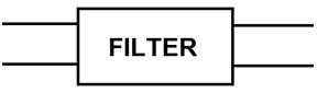
Figure 2: Two conductor filter
If the signals appearing at the terminals of the filter are different as the ones shown in Figure 3, then the signals are in symmetrical form.

Figure 3: Symmetric (Differential) mode: Different signals appearing at each terminal of a filter and shown together for comparison.
Asymmetrical (common mode) signals are those that appear equally at the same time and in the same direction on all the conductors going into a filter in a shielded enclosure. These signals use the ground as a return path and all other conductors carry the signal into the enclosure in the exact same proportion. If the signals present at each terminal are exactly the same as in Figure 4, then the signals are said to appear in asymmetrical or common mode [2].
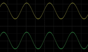
Figure 4: Assymetric (Common) mode: Same signals appearing at each terminal of a filter and shown separately for comparison.
Now that we have defined the two types of signals that may be present in conductors, let us now consider the types of filters used to remove these signals.
Symmetric Filters
Symmetric filter designs (SFDs) consist of discrete inductive and capacitive elements arranged in such a way so as to remove unwanted signals from a particular conductor. Inductors provide a high series impedance to unwanted signals. Capacitors work in an opposite manner and short unwanted signals to ground; they provide a low impedance path for high frequencies. Together they provide attenuation to unwanted signals appearing on those conductors [1]. These components are not shared with any other elements in another conductor. Consider Figure 5 and notice the distribution of components along the line to load of current flow. This current flow does not interact with the current flow of the second line of a two line filter, in other words, each filtered line is independent of each other. The inductor of a symmetric filter has one line coming in and one line coming out as shown in Figure 6.

Figure 5: Schematic of a aymmetric filter, each line independent of each other
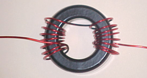
Figure 6: Symmetric inductor
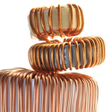
Figure 7 shows what an actual symmetric filter looks like with independent component lines for filtering of each power line coming in. A typical procurement specification for facility power filters for use in EMC, defense, and military specify that, “Each filter unit (insert) shall be capable of being mounted individually… and shall include one filter for each phase conductor of the power line and neutral conductor.” [1]

Figure 7: Showing two versions of an actual filter with independent filtered lines
One would expect, as the name implies, that a symmetric filter can remove symmetric signals, but as an added benefit a symmetric filter can also remove asymmetric signals. The reason for this may not be too obvious. But let’s take one filter line at a time.
Here, there is one signal and one filter line as in Figure 8. The filter line removes any unwanted signal regardless of amplitude or shape and does not see or care about what is present in another line. A second filtered line may be seeing the exact same signal or a different one, but because each signal is being dealt with independently, all unwanted signals present will be removed as shown in Figure 9. SFDs reject asymmetric mode signals by default. This is because each line of the differential filter will be equipped with the discrete elements necessary to remove signals present in those conductors whether they are common mode or differential mode.
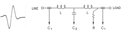
Figure 8: Filter element removing ANY signal from line
![]()
Figure 9: Different (symmetric) signals or same (asymmetric) are removed by independent filtered elements in each line (symmetric filter) regardles of type of signals present.
A filter can be tested for either symmetrical or asymmetrical performance. Meaning that a particular filter can be tested to see how well it removes symmetric or asymmetric signals. This is done by injecting into the filter signals that are different on each conductor or signals that are the same on each conductor, as would be expected. The graph in Figure 10 illustrates that a symmetric filter can remove both types of signals.
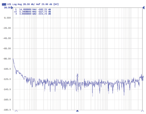
Figure 10: Showing a symmetric filter tested for both symmetric and asymmetirc performance producing the same response
SFDs are especially useful in environments where the signals present are chaotic and unpredictable and may arrive in different amplitudes, phases and shapes. Another very useful aspect of this type of filter is that it can be used to remove signals of very low frequencies. EMC testing, such as that found in standards like MIL-STD-461 and -462, requires a quiet RF environment down to 9 kHz. Military and defense applications, in particular, often cite TEMPEST requirements for their shielded facilities and these include low frequency filtering. TEMPEST requirements typically mandate high levels of attenuation (removal) of low frequencies as far down as 14 kHz or even 9 or 10 kHz [1]. Symmetric filters are not only well-suited for use in these environments, but are the only choice given some of the short comings of asymmetric filters.
Symmetric filters are typically bigger than asymmetric filters because each line must have individual inductors, which also makes them more expensive. Symmetric filters also dissipate more power than asymmetric filters of the same capacity. Asymmetric filters share inductor cores with other lines, reducing needed space and cost. But one must keep in mind that saving on size, cost, and power dissipation is not a bargain if used on the wrong application. Asymmetric filters should not be used on EMC, TEMPEST or HEMP applications.
Asymmetric Filters
Asymmetric filter designs (AFDs) also consist of inductive and capacitive elements as shown in Figure 11, but arranged such that the lines share the inductor core removing unwanted signals only when they appear in asymmetric or common mode.

Figure 11: Asymmetric filters share inductors between lines
Consider the inductor of a two line filter as in Figure 12. It can be seen that the two lines of the filter are made to pass though the inductor core and thus sharing the core between the lines. This has the beneficial effect of being able to leverage the flux cancelling effect of such arrangement and lower the core losses. That is, as current flows in one wire in one direction the other wire has current flowing in the opposite direction. This has the effect of cancelling the magnetic flux generated by the flow of current and the core operates at lower losses.
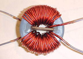
Figure 12: Asymmetric Inductor (two or more lines through it)
When the signals appear differently, as is the case when power goes into the inductor and out through the other line in opposite direction (see Figure 13), the inductor does not present a significant opposition to the signals and they pass right through the inductor [2].

Figure 13: Power signals appearing differentlially in a common mode core
While this is beneficial at power frequencies, it is not so with other signals present in the lines. Essentially, the inductor looks like a very small inductor when symmetric signals are present and only appears like a huge inductor to asymmetric signals. A smaller inductor in terms of capacity allows for signals to go through while a big inductor stops low frequencies. This can be seen clearly when measuring an asymmetric filter for symmetric (DM) and asymmetric (CM) performance as in Figure 14.
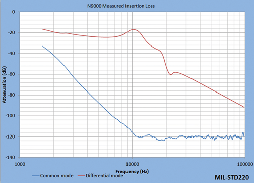
Figure 14: Comparison between CM and DM performance of an asymmetric filter
The common mode filter is mainly used in low amperage electronic circuitry to eliminate radiated emissions caused by electronic components and their layout. Equipment needs to meet radiated emissions mandated by EMC standards and thus much of what is found in equipment such as computers, televisions and other commercial electronic items are common mode filters. But when it comes to industrial, military or other applications where a high degree of attenuation to unwanted signals is needed, symmetric filters are the right choice.
As previously stated symmetric filters are typically bigger than asymmetric filters, making them more expensive; because as we have seen, symmetric filters do not share inductor cores which would reduce space. We also stated that symmetric filters also dissipate more power than asymmetric filters of the same capacity. But there are other issues with the use of asymmetric filters, such as the need for an electrically balanced system and paralleling considerations.
In AFDs not only must the signals to be rejected appear the same at the filter’s input, but the power current in which the filter operates must be balanced. Consider a three phase system, for example. The loads on each phase must be the same in order for the asymmetric filter to operate normally. Any imbalance in the system will cause added heat to the common core, reducing the life of the filter and significant loss of rejection and HEMP protection capabilities.
Paralleling asymmetric filters to obtain higher amperage lines requires a tandem paralleling schema which increases cable lengths and contributes to the appearance of symmetric signals in the lines and can potentially imbalance the system. Symmetric signals then would get through the filter. All these factors make paralleling an asymmetric filter an undesirable solution. A symmetric filter can be paralleled more easily and will not suffer from imbalance or rejection performance issues. Each element can be paralleled adjacent to another and matched accordingly with no detrimental effects in the system.
Filters for TEMPEST and HEMP
The term TEMPEST is often used for the field of emission security. The term TEMPEST is a codename to secure government and military electronic communications equipment from potential eavesdroppers that could intercept and interpret those signals. There are some guidelines on how to achieve TEMPEST protection for an installation. These include the shielding effectiveness of a chamber containing sensitive equipment and the insertion loss (attenuation) of the filters in the conductors coming in and out of such chambers. While the levels and degrees of protection may vary according to the threat level the majority of U.S. military and government installations use NSA 65-6/94-106 when specifying the required degree of protection [1]. This states that all conductors into a chamber should be attenuated 100dB from at least 14 kHz as seen in Figure 15.
![]()
Figure 15: TEMPEST requires that all lines in or out of a facility meet a high degree of attenuation (insertion loss).
When using asymmetric filters, the assumption is made that any radiated RF would couple equally and balance into all conductors at once. But in real life no two signals are ever identical or perfectly balanced and any imbalance in a system carrying common mode signals can create a voltage difference between the conductors giving rise to differential signals. And as we have discussed above, a common mode inductor would allow passage of differential signals. If such TEMPEST system relies on asymmetric only filters, or ones with very little symmetric attenuation, the result would be that these signals would pass through into (or out of) the enclosure. As can be seen this is a significant problem in defense and military TEMPEST applications in which the coupling of signals in the inside of a shielded enclosure is rather chaotic and unpredictable and can be present in both symmetric and asymmetric forms. In such cases, filters should be able to reject both symmetric and asymmetric signals.
Banking on the remote chance that a High-Altitude Electromagnetic Pulse (HEMP) will arrive equally on all power lines (see Figure 16) seems unwise. As we have seen, AFDs depend upon signals arriving equally on its inputs to be able to reject those signals. That signals will arrive just right for an asymmetric filter to stop them is highly unlikely given atmospheric conditions, propagation of the wave, number of electrons released, distance between power lines, etc. In HEMP applications, the EMP will arrive chaotically and unpredictably at the Points of Entry (POE). Filters should be able to reject symmetric signals. If asymmetric only filtering is used, not only will the signals get through, but these unpredictable signals (some of which could be of very high amperage) could cause an imbalance in the common core of the asymmetric filter which would lead to instantaneous saturation of the core(s) and total loss of protection to any form of electromagnetic energy.
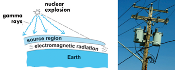
Figure 16: Coupling or electromagnetic energy from an EMP depends on many unpredictable factors.
Conclusion
It has been shown that symmetric (differential mode) and asymmetric (common mode) signals are different types of signals that may be present in conductors. It is also clear that these may be removed by using symmetric filters. It is been demonstrated that asymmetric filters can only remove asymmetric signals. While asymmetric filters are generally physically smaller and less expensive (due the reduced number of components) than the symmetric filters, the use of asymmetric filters must be very carefully evaluated or unwanted differential mode signals may inadvertently pass through the filtering network and compromise overall system performance.
A critical point is that filters designed to reject symmetric noise can also reject asymmetric mode signals by default. Unfortunately AFDs can only remove common mode signals due to the sharing of components between lines, which offers very little if any symmetric attenuation. This is why AFDs only come in packages of one box with terminals whereas differential mode filtering may also be offered as discrete individual filter (inserts) elements. That is, the differential filter does not need to share a reactive core with other lines in order to remove unwanted signals, and thus can be packaged in individual lines as in Figure 7 above. The packaging issue brings up the fact that in the event of a filter system failure, replacing symmetrical filters is much more cost effective than removing an entire three phase filter box after one line has suffered damage. In addition, the down time of replacing one element is much less than that of replacing an entire asymmetric unit.
| Symmetric Filter Designs | Asymmetric Filter Designs | |
| Tempest | Yes | No |
| Tempest/HEMP | Yes | No |
| HEMP/IEMI | Yes | No |
| Common mode | Yes | Yes |
| Differential mode | Yes | No |
| Accepts Unbalanced loads | Yes | No |
| Easy parallelization | Yes | No |
| Easy to replace filter elements | Yes | No |
| Reduced down time after failure | Yes | No |
The table above illustrates the recommended uses for symmetric and asymmetric filters. ![]()
References
- L. Hemming, Architecturon Techniques in Electronic Systems, 2nd, ed. Wiley-Interscience, John Wiley and Sons, New Jersey: 1992.
- H. W. Ott, Noise Reduction Techniques in Electronic Systems, 2nd, ed. Wiley-Interscience, John Wiley and Sons, New Jersey: 1992.
 |
Sergio N. Longoria, BSEE studied at the Instituto Tecnológico y de Estudios Superiores de Monterrey. He is a US Air Force veteran and has over 20 years of experience in the electronics industry, 12 of which in the design of power filters including special military and defense applications. He has been with ETS-Lindgren, Inc. Since 2001 and is currently the Technical Product Line Manager for Filters. He can be reached at Sergio.longoria@ets-lindgren.com. |