
There is nothing worse than believing the correct voltage is being applied to a Device Under Test (DUT), only to find out a cable is broken and the only thing that has been tested is the hipot tester itself and part of the cable. This is especially true if this fault was not caught in time and product has already been shipped to the customer. While a skilled operator may notice a difference in leakage, collecting data and evaluating the data on a regular basis may also reduce such an error. However, there are other precautions that may be put in place to ensure the safety test is performed correctly. Two common product safety tests seen in production are the dielectric strength test (commonly referred to as hipot) and a ground test. The hipot test stresses the insulation of a product, while the ground test ensures proper ground connections within the product. The two most common ground tests are ground bond and ground continuity. This article will discuss these two common tests, as well as safeguards to ensure proper testing.
Dielectric Withstand Test
A dielectric strength test, commonly called a “dielectric withstand”, “high potential”, or “hipot” test, is a stress test of the insulation barrier of a device under test. The dielectric barrier protects the user from exposure to dangerous electrical potentials. The most common points of application for a dielectric withstand test are between AC primary circuits and low voltage secondary circuits, as well as between AC primary circuits and user-accessible conductive parts/ground.
Such a test applies a voltage to the DUT that is much higher than normal operating voltage, typically 1000V AC plus twice the normal operating voltage. Therefore, for a household appliance designed to operate at 120V AC or 240V AC, the test voltage is usually about 1250 to 1500V AC. Voltage is applied to the DUT and any current leaking through the insulation is measured.
When performing this test, it is important to ensure the connection between the hipot tester and the DUT. A hipot test can produce a false pass if the high voltage cable between the DUT and tester is broken or unconnected. The test is designed to stress the insulation of the DUT. If the output test lead is broken the DUT will not be exposed to the high voltage, thus the insulation will not be stressed and the test will pass.
Programming Limits
During an AC hipot test there is typically some leakage current due to the capacitive characteristics of the DUT. Hipot on a three pronged device is performed with voltage applied to line and neutral tied together, measuring the leakage to ground. If the device under test has a capacitance of 100pF between these connections, there will naturally be 47uA of leakage for a 1250V hipot test. This can easily be calculated using ohms law.
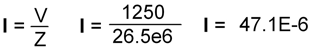
Knowing that the leakage of the DUT must be at least 47uA based on the design of the product, a low limit can be used to ensure the leakage at a minimum reaches a specific level. Most digital hipot testers include programmable high and low limits. The high limit being the maximum amount of leakage current allowed and the low limit the minimum amount of current. If the test lead is broken the minimum amount of leakage current will not be present, resulting in a Fail Low. Figure 1 shows Pass Fail ranges.
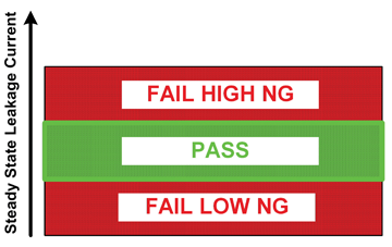
Figure 1: Pass Fail ranges for a hipot test
Setting a low limit to ensure connection is a valid option for AC hipot testing. However, determining whether a product is attached during a DC hipot test is more challenging. Often the leakage from a DC hipot is zero or in the low microAmps. Setting a low limit is not feasible.
One solution is to first perform a low voltage AC hipot test, with a low limit programmed to ensure the connection, to measure the leakage current, and then to perform the DC hipot. By performing the test at a low AC hipot voltage, the DUT is not being stressed twice with high voltage, the result of which could produce unpredictable results. It also allows for an AC test to actually run. Typically DC hipot is performed because the leakage from capacitors within the DUT exceeds the AC specifications of the tester. By lowering the voltage the leakage is reduced to a manageable current within the tester’s limit.
Charge Current
Setting low limits is not the only solution to ensure connections. Some testers on the market contain a function to measure the charge current during a DC hipot test. A limit can be set around the charge current to ensure there is an in-rush of current at the beginning of the test. This acts the same as setting a low limit. If no charge current is present the test fails.
Measuring Capacitance
Other testers measure the capacitance of the device under test and compare the measurement with a known value. The device under test contains some capacitance (Cx) as shown in Figure 2. The tester measures the capacitive load of the DUT to determine whether the connection is good.
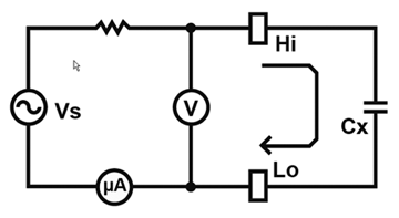
Figure 2: Voltage applied to a DUT with capacitance Cx
If the connection is open, additional capacitance (Cc) will be measured (Cm) and the total capacitive load will be less the capacitance of the product under test, resulting in an open circuit Failure. Figure 3 shows Cc added in series with Cx .
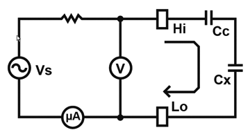
Figure 3: Voltage applied to DUT with capacitance Cx and additional open circuit capacitance Cc
A hipot test will pass if not connected to the DUT, if preventions such as low limits, measuring charge current or capacitance have not been put in place. The ground test however, will fail if no connection is in place.
Ground Test
Ground continuity is performed using a low DC current source, typically less than 1 Amp, between the ground blade on the power cord and any exposed metal on the product. Ground bond is not always required for production testing but some manufacturers choose this test over ground continuity because it may detect a problem in the ground circuit that the continuity test may pass. The ground bond test applies high current, usually 25 – 40 Amps, to the same ground path as the continuity test. The resistance of the ground path, normally less than 100 mW is measured using a Kelvin connection. Not only does ground bond verify the continuity but it verifies the integrity of the circuit and its capability to carry high current.
Since current must have a path to travel, if connection is not made during the ground bond or ground continuity test the test will fail. The test result on most digital testers today would be a high failure or current overload. Broken leads are not usually an issue when it comes to the ground test. If the lead is broken, the test will fail. If there is an internal short within the tester, the test will pass. Knowing the typical resistance of the device under test can help raise flags if the expected resistance drops. The use of a load box will ensure the tester is measuring properly and no internal faults have occurred. This holds true for both hipot and ground bond.
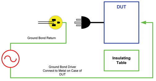
Figure 4: Typical ground bond test
Load Box
A load box is a simple box which consists of high voltage resistors with values based upon the test specification in which the hipot tester is being used. The resistors in the load box do not have to be precision resistors or have an accurate calibration. They are only intended to check the tester, not verify or calibrate it. The box typically contains two connections, a Pass and a Fail. When attached to Pass the intent is for the hipot to Pass. Conversely, when connected to Fail, the hipot shall fail. Recently the demand for load boxes has increased as Nationally Recognized Test Laboratories (NRTLs) such as Underwriters Laboratories are requiring a daily load box check.
Load Box Example
An appliance manufacturer has the hipot tester configured for a 1200V hipot test. The high limit is programmed for 10mA. The resistor from ground to Pass would need to be greater than 120kΩ. Let’s say, the manufacturer chooses to use a 140kΩ resistor. The user would expect to have his hipot tester measure 8.5mA, which would be considered a PASS given the set 10mA high limit. The Fail resistor would need to be less than 120kΩ. The manufacturer chooses a 100kΩ resistor. The 100kΩ load with 1200V produces 12mA of current, resulting in a FAIL.
Figure 5 illustrates how to calculate the PASS and FAIL current values based on the manufacturer’s specifications of a 1200V hipot test with a 10mA high limit.
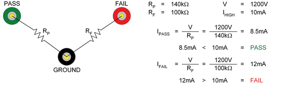
Figure 5: Resistor configuration for a hipot load box
A load box can also be used to verify the ground bond function of the tester. For a ground bond test high current resistor values of 50mΩ and 150mΩ are used. The most common ground bond test is performed at 25A, the resistance shall not exceed 100mΩ. Ground Bond (GB) verification is performed from the ground blade of the power entry adapter to the binding post. Connecting to the red binding post and to the FAIL power entry module will result in a failure in the GB test because the actual value of resistance (150mΩ) is greater than the set limit of 100mΩ. The pass circuit has the 50mΩ resistor, so in connecting between the green binding post and the PASS power entry module, the GB test will pass.
One load box can be used for both hipot and ground bond. Figure 6 shows a load box configured for hipot and ground bond. Performing the load box test to Pass will ensure the tester is capable of measuring a good product. Attaching to the Fail will ensure the tester will produce a failure if the current exceeds the programmed limit for hipot or the resistance exceeds the limit for ground bond.
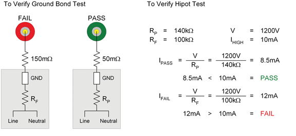
Figure 6: Resistor configuration for hipot and ground bond load box
Choosing the correct resistor for a high voltage application requires some thought. It is necessary to take the maximum voltage rating, voltage coefficient and power rating into consideration when specifying resistors for a load box.
The voltage rating is the maximum voltage that can be applied to the resistor without causing damage to the resistor due to arcing or breakdown.
The voltage coefficient expresses the change in resistance value due to a change in the amount of applied voltage. The voltage coefficient for a resistor is normally expressed in ppm/Volt and is always negative. This means the higher the applied voltage, the lower the resistance value.
The power rating defines how much power the resistor can dissipate without damaging the resistor. Calculate the power being dissipated at the intended operating voltage. Do not assume that just because the resistor is being used under the maximum voltage rating that there will not be an issue. It is always advisable to calculate the power using P=V2/R, where V is the test voltage and R is value of the resistor, P = I2*R can also be used where I is the current through the resistor.
The required power dissipation for the load box example above would be P = (1200V)2/ 100e3 = 14.4W for the fail condition and P = (1200)2/140e3 = 10.28W for the pass condition. Finding a 15 or 20 Watt resistor may be difficult. Vishay RS10 resistors are readily available in a variety of values; this series by Vishay is rated for 10W. Using multiple resistors in series will help reduce the power and voltage requirements, as only half the voltage would be applied to each resistor.
Performing a daily load box check will verify the tester is operating properly at the time the test is performed. However, it will not ensure the cables won’t break at some point during the day. It may not be until the next morning when the load box check is performed until a fault in cabling is recognized.
Data Collection
Collecting data while testing will provide history if an issue occurs. For years, hipot and ground bond or continuity were simple pass/fail tests. Today, more and more manufacturers have strayed away from the traditional pass fail result and are recording actual measurement values. Hand recording the values on a product traveler will provide operator awareness as to the leakage current, for hipot, or resistance for the ground measurement. If the values were to differ significantly as in the case of a broken wire, a good operator will identify there is an issue. Hand recording data has its downfalls as human error increases the likelihood of an error. Further, manually digging through the travelers to identify if and when an issue occurred is time-consuming and tedious.
Hipot testers now provide flexibility with data collection by connecting to a PC so that data does not need to be manually recorded. Testers have command protocols to be used in custom program which allow full control over the tester and its results. Software or sample programs, as well as Labview Drivers, are generally available for most testers on the market today. Recording data electronically provides the benefit of easily retrieving test results and viewing test history. Imagine if a broken cable goes undetected and product ships. Having data to track when the problem occurred is extremely helpful to any manufacturer.
Data collection likely will not prevent a hipot test from passing if the high voltage cable breaks, however it will help assist with the aftermath of the issue at hand. It will also provide trending so safeguards such as setting a low limit can be put in place easily. There are options to ensure the test is being performed correctly. Unfortunately, many companies wait for a breakdown before they implement safeguards. ![]()