Injection of audio frequency ripple on equipment input power conductors has a long history, going back to 1953 (MIL‑I‑6181B) in the United States military, and at least as far back as 1961 in commercial aviation (RTCA/DO‑108). Audio frequency injection has been accomplished by inserting the secondary windings of a coupling (isolation) transformer in series with the power conductor to the test sample. While various transformers had been used prior to the 1960s, one has become standard since 1963. That Model is the Solar Electronics Model 6220, designed in 1962 and accepted by the United States Air Force in 1963 as being superior to previously used injection transformers. [1]
This device, which may be found in every EMI test facility that performs testing for automotive, aviation, or military applications, is admirably suited to the task, with perhaps one minor drawback. That being it inserts about one millihenry of inductance in series with the power line unless the primary side is properly loaded so as to shunt this leakage inductance. Such a large inductance in series with the power source can cause instability and even damage to a switched mode power supply lacking adequate decoupling from the power source.
Unlike the other markets mentioned previously, the space industry often conducts qualification testing on flight equipment, and is thus leery of anything that could have an even remote possibility of damaging flight hardware. The Jet Propulsion Laboratory EMI test facility has gone so far as to develop their own audio frequency injection technique which doesn’t require the coupling transformer. [2]
However, such heroic measures are actually unnecessary for space equipment. An alternative injection technique similar to modern bulk current injection technology was developed for the Apollo program Lunar Excursion Module (LEM) in the mid‑1960s. It is this forgotten technique that is exhumed and investigated herein.
Background
The 1971 Solar Electronics catalog contains the following verbatim text on the reverse side of the ubiquitous Solar Model 6741‑1 current probe data sheet:
Audio Frequency Induction Probes for LEM Testing
A clever new idea introduced by Grumman Specification LSP‑530‑001 for inducing up to one volt of audio on each wire inserted in the window of a split toroid for susceptibility testing. Includes monitoring winding to show how much audio is being induced on the wires being tested. Designed for 4 ohm audio amplifier output. 30 Hz to 15 KHz. Type 6541‑1. 1 1/4 ” I.D.
References to LSP‑530‑001 [3] appear in other NASA/Apollo publications as early as 1963. [4] The Solar Model 6541‑1 means that the design was done in 1965; the first two digits of a Solar Model number being the last two digits of the year it was designed, in the last century.
The Solar Electronics data sheet for the 6541‑1 lists the following pertinent information (verbatim):
“The Solar Electronics Type 6541‑1 Induction Probe has been designed to provide induced signals from a 100 watt audio amplifier with a four ohm output impedance over the range of 20 Hz to 15 kHz. Such a test is required by paragraph 4.5.3 of LEM Specification LSP‑530‑001.
Using the Type 6541‑1 Induction Probe, it is also possible to perform to the specification using the eight ohm output of a 60 watt audio amplifier, with some degradation of waveform at frequencies below 100 Hz. At low frequencies, the wave shape may be improved by lowering the output impedance to less than four ohms by connecting to the four ohm output tap and adding a fixed resistance load.”
Other important information is that the Induction Probe saturation current is 35 Amps direct current, and most importantly for our investigation (verbatim), “the probe adds approximately 0.01 ohm in series with each wire passing through the probe.” The probe, shown in Figure 1, is physically similar to the well‑known Solar Model 6741‑1 current probe, using the same enclosure with only a different multi‑pin connector instead of a bnc.
It should be understood that the purpose of this new technique in LSP‑530‑001 was not to replace the coupling transformer injection technique that was included in it and was substantially the same as that used universally today. Instead, injection using the Solar 6541‑1 was aimed at common mode injection on signal cables, similar to how we perform MIL‑STD‑461D/E/F CS114 and RTCA/DO‑160 section 20 rf conducted susceptibility testing today. The limit was much less stringent than the requirement for audio injection on equipment power input. The two LSP‑530‑001 limits are graphed together for comparison in Figure 2. The two curves are not completely an apples‑to‑apples comparison, because the “CS01‑like” requirement is 3 Vrms open circuit, with no mention of the signal source impedance, whereas the bulk current injection‑like limit is measured as induced on the cable‑under‑test (CUT).
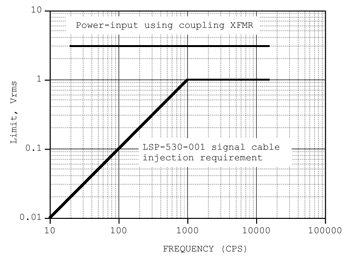
Figure 2: LSP‑530‑001 power input & signal bundle audio susceptibility limits
However, a feel for the difference between the open‑circuit and cable‑induced limits can be obtained by noting that LSP‑530‑001 specifically references a McIntosh 60 audio power amplifier using the 8 ohm tap for the signal cable test. The McIntosh C60 amplifier shown in Figure 3 was specified to have a damping factor of 12 or better on the 4, 8, and 16 ohm taps so that the source impedance was well under one ohm. And audio frequency conducted susceptibility testing for power inputs was generally specified to have a 0.5 ohm or lower source impedance in the days running up to and including MIL‑STD‑462. [3] Which means that for most applications, the open‑circuit and loaded potentials wouldn’t have differed greatly.

Figure 3: McIntosh MC60 amplifier specified for use with Solar 6541‑1 in LSP‑530‑001
Rationale for Use of the Alternate Injection Technique for Spacecraft Equipment
It will be noted that whereas the Model 6220 injection transformer is capable of injecting at least 6.3 Vrms using a 100 watt amplifier, the Model 6541‑1 can only inject up to 1 Vrms (see graph, below). Clearly, the Model 6541‑1 is not suitable for testing to MIL‑STD‑461 CS101, or RTCA/DO‑160 section 18. However, the ripple levels in these standards derive from electro‑mechanical power generation, where an engine of one sort or another turns a shaft that provides motive power to an electrical generator. Such power sources have inherent ripple, viz. MIL‑STD‑704, all revisions. MIL‑STD‑461 CS101 in particular is written to provide a margin with respect to MIL‑STD‑704. [5] RTCA/DO‑160 section 18 also refers to harmonics of the power frequency as the source of ripple in all versions since and including RTCA/DO‑160B in 1984. Boeing standard D6‑16050‑2, dated 1977, also refers to power generating equipment as the source of audio frequency ripple requirements.
But most spacecraft are different. Especially those operating in Earth orbit, or within Earth’s orbit of the Sun, tend to use solar panel arrays that charge a battery. An electrical power subsystem based on solar charging has no inherent ripple, at least not at audio frequencies. The only source of audio frequency ripple is load‑induced effects, and these are minor with a battery‑dominated bus. The United States National Space Transportation System (Space Shuttle) quotes 0.8 Volts peak‑to‑peak in a dc to 50 MHz bandwidth, with no more than 0.4 Volts peak‑to peak at any discrete frequency, with the bus resistively loaded (i.e., no load‑induced effects). [6] The Space Shuttle uses fuel cells in lieu of batteries and solar arrays. Obsolete MIL‑STD‑1541A (dated 1987) required time domain ripple to be less than 0.5 Volts peak‑peak. The International Space Station Power quality specification [7] required a maximum of 3 Volts peak‑peak ripple in the time domain (20 MHz bandwidth), and no more than 0.3 Vrms ripple at any discrete frequency resistively loaded, even though this power was sent through a dc/dc switched mode converter between the solar arrays and the electrical bus. The orbiting x‑ray observatory Chandra specified 1.5 Vpeak‑peak time domain over a 1 Hz to 1 MHz bandwidth. At the current time, the orbiting infrared observatory James Webb Space Telescope is looking at under 1 Volt peak‑peak ripple in the time domain and a 1 Vrms CS01 limit.
The graph in Figure 4 shows ripple limits for 28 Vdc power from MIL‑STD‑704, revisions A‑F, vs. the maximum ripple the Solar 6541‑1 injection clamp can induce in 0.5 ohms. It will be seen that except for the obsolete A revision, the Solar 6541‑1 performance suffices except at the very low end below 100 Hz, and it is precisely that very low end that simply won’t be there, meaning the ripple on a battery dominated spacecraft 28 Vdc bus.
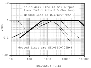
Figure 4: Maximum potential induced on 0.5 ohm load using Solar 6541‑1 as intended. Compare to various MIL‑STD‑704 28 Vdc ripple limits.
Modernizing the Technique
While the Solar 6541‑1 performs as needed for the LSP‑530‑001 requirement, it complains loudly (core vibration – “singing”) when pushed to the maximum levels in the above graph. And while the author feels the Figure 4 levels available from the 6541‑1 should suffice for spacecraft applications with a battery‑dominated bus, it is possible to modify the clamp to get 1 Vrms across 0.5 ohms over a wider range. The clamp is a twenty‑turn primary, single turn secondary transformer. As such, it is a step‑down transformer with a 400:1 impedance transformation. Since the audio amplifier output is no more than 2.4 ohms (Solar audio Amps for conducted susceptibility testing) to well below an ohm (the McIntosh C60), this much step‑down is not useful. Pulling ten turns through the clamp window converts the step‑down ratio to the same as that for the 6220 coupling transformer, and allows the cited 1 Vrms to be induced across 0.5 ohms from 30 Hz to 80 kHz.

Figure 5: The 6541‑1, center, with ten turns through the window is driven from the 100 watt Solar 6550‑1 power audio oscillator and induces the oscilloscope‑measured potential across the two parallel 1 ohm resistors in the foreground.
Ten turns, in addition to providing a 2:1 turns ratio, also provides about 100 uH secondary winding inductance, which is 10% that of the 6220. That 10% value was used as a benchmark. More turns give better performance, but at the cost of higher secondary inductance. The whole point of the modernization investigation was to finesse the minimum amount of secondary inductance that would result in the ability to inject the required potential into 0.5 ohm down to 30 Hz. It was felt that keeping that inductance to 100 uH should suffice to allay fears of damage to switching converters. Note that 100 uH is the power source impedance seen by any test sample undergoing MIL‑STD‑461D/E/F qualification. In other words, a robust power supply and filter design ought to be able to operate stably from a 100 uH power source impedance.
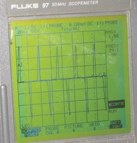
Figure 6a: 1 Vrms injected across 0.5 ohm at 30 Hz. Note considerable distortion, which can be ameliorated by more turns.
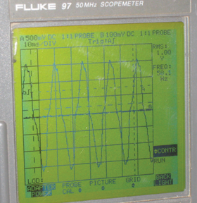
Figure 6b: 1 Vrms injected across 0.5 ohm at 60 Hz. Note distortion, which can be ameliorated by more turns.

Figure 6c: 1 Vrms injected across 0.5 ohm at 80 kHz.
Conclusion
A “space‑race” era EMI test technique has been discovered and examined and modified to provide a safer technique to inject audio frequency ripple on dc power lines. The injection clamp is still available from Solar Electronics, and it is the author’s hope that the technique described herein is adopted as an alternate audio frequency test technique in such standards as the Goddard Space Flight Center’s General Environmental Verification Specification (GEVS), the American Institute of Aeronautics and Astronautics (AIAA) S‑121‑2009 Electromagnetic Compatibility Requirements for Space Equipment and Systems and other EMI control requirements with a spacecraft focus. ![]()
Acknowledgment
The author would like to thank EMC engineers at the Marshall Space Flight Center for sifting through old records and finding a copy of LSP‑530‑001.
References
- ASNPRE‑1/34257, June 6, 1963. Subject: Isolation Transformer, Solar Model 6220‑1.
- A. Whittlesey & K. Erickson, “A Stable CS01 Tester for Switch Mode Power Supplies,” 2006 IEEE EMC Symposium Record.
- Grumman Aircraft Engineering Corporation Specification No. LSP‑530‑001, 24 June 1963, “Electromagnetic Interference Control Requirements, General Specification for.”
- Grumman Aircraft Engineering Corporation Report No. LED‑520‑1C, 15 May 1963, “Design Criteria and Environments LEM” submitted under NAS Contract 9‑1100.
- See the Rationale Appendix for CS101 in any version of MIL‑STD‑461 since 1993 (D, E, & F revisions).
- ICD‑2‑19001, revision K, “Shuttle Orbiter/Cargo Standard Interfaces,” 1 August 1991, Section 7.3.7.1, page 7H‑1.
- SSP 30482 Volume 1: Electrical Power System Electrical Performance Specifications, July 1997.
Ken Javor has worked in the EMC industry for thirty years. He is a consultant to government and industry, runs a pre‑compliance EMI test facility, and curates the Museum of EMC Antiquities, a collection of radios and instruments that were important in the development of the discipline, as well as a library of important documentation. Mr. Javor is an industry representative to the Tri‑Service Working Groups that write MIL‑STD‑464 and MIL‑STD‑461. He has published numerous papers and is the author of a handbook on EMI requirements and test methods. Mr. Javor can be contacted at ken.javor@emccompliance.com.
