Conducted emissions are the noise currents generated by the Device-Under-Test (DUT) that propagate through the power cord or harness to other components/systems or power grid. These noise currents can be measured using either the voltage method or the current method. This article describes the voltage method of the conducted emissions measurements. Section 1 describes the ac conducted emission measurements while Section 2 is devoted to the dc measurements.
AC Conducted Emissions Measurements
FCC Part 15 and CISPR 22 standard set the limits on the ac conducted emissions. CISPR 25, MIL-STD-461 (and many other standards) set the limits on the dc conducted emissions. To measure conducted emissions an Artificial Network (AN) or the Line Impedance Stabilization Network (LISN) is used [1], [2].
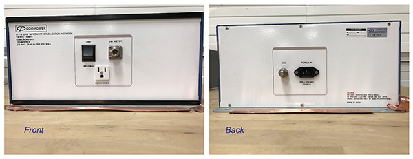
The ac LISN comes in a dual configuration allowing for the Line and Neutral noise current measurement by simply flipping the switch on the LISN. Such a LISN is shown in Figure 1.
The schematic of this dual LISN is shown in Figure 2.

We often use a simplified model, where the LISN is represented as a 50 Ω resistor. Such a model is shown in Figure 3.
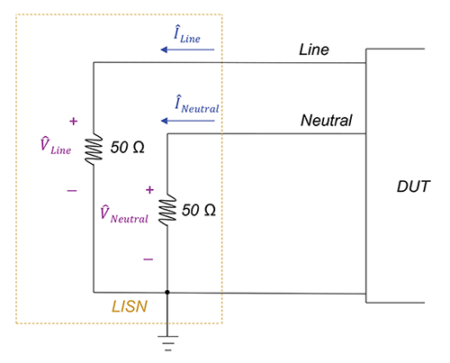
The method of conducted emissions measurements described in this article is called the voltage method because even though we are interested in the noise currents ILine and INeutral, we actually measure the noise voltages VLine and VNeutral. Obviously, the noise voltages and noise currents are related by

FCC and CISPR 22 conducted emissions measurements are performed in the frequency range of 150 kHz – 30 MHz. The allowable limits for both Class a and Class B devices are shown in Figure 4.

Measurements of the conducted emissions can be performed using one of two different setups. The first one involves two conducting planes, horizontal and vertical, as shown in Figure 5a. The details of the test setup (for table-top devices) are shown in Figure 5b, (for clarity, the vertical plane is not shown).

Figure 6 shows an actual DUT (laptop) arrangement according to the FCC/CISPR 22 specifications.

A sample conducted emission signatures of the Line and Neutral noise and the corresponding limits are shown in Figure 7 and Figure 8, respectively.


DC Conducted Emissions Measurements
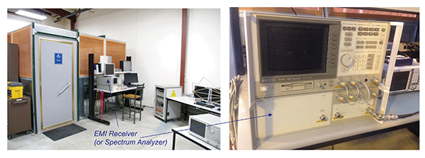
The measurement setup and emissions limits on the dc conducted emissions are specified by many standards. To facilitate our discussion we will concentrate on the CISPR 25 (automotive) standard. This standard requires the conducted emissions measurements be taken in a shielded enclosure like the one shown in Figure 9.
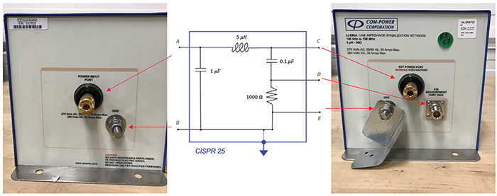
To measure conducted emissions the LISN shown in Figure 10 is used.

Its schematic is shown in Figure 11.

Figure 12 maps the schematic to the LISN physical ports.
CISPR 25 conducted emissions measurements are performed in the frequency range of 100 kHz – 108 MHz. The allowable limits for the five different classes of devices for the voltage method of conducted emissions measurements are shown in Figure 13.

The measurement setup inside the shielded enclosure for the conducted emissions measurements is shown in Figure 14.

The conducted emissions measurements are performed for both the battery line and the ground line. Thus, two dc LISNs are utilized. When the measurement is taken on the particular line, the LISN associated with that line is connected to the spectrum analyzer and measurement port of the other LISN is terminated in a 50 Ω load. The details of the connections are shown in Figures. 15 and 16.


Figure 17 shows the physical arrangement of the LISNs inside the shielded enclosure.

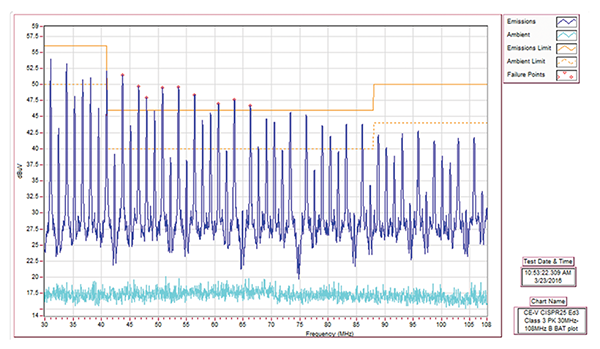
Figure 18 shows a sample measurement for a DUT which failed the conducted emission test, while Figure 19 shows the result for a device which passed it.

Acknowledgement
The author would like to thank Jim Teune of E3 Compliance LLC for his expert advice.
References
- Bogdan Adamczyk and Jim Teune, “Topology and Characterization of a DC Line Impedance Stabilization Network,” In Compliance Magazine, July 2017.
- Bogdan Adamczyk, Foundations of Electromagnetic Compatibility with Practical Applications, Wiley, 2017.
