Impact of a Guard Trace
This is the second article of a two-article series devoted to the topic of crosstalk between PCB traces. In the first article [1], we varied the circuit topology (the distance between traces and the distance to the ground plane) and investigated its impact on crosstalk, both in time and frequency domains. In this article, we investigate the impact of a guard trace on crosstalk reduction. This topic was previously discussed in [2], where we used an earlier-generation PCB and concentrated on signal integrity or the time domain measurements. This article presents measurements taken with the latest‑generation PCB, both in time and frequency domains. Frequency domain measurements are taken with a near-field scanner using an H-field probe.
PCB Topology with a Guard Trace
In this study, the PCB traces were 30 mils from each other and 52 mils from the ground plane. The traces were separated by a guard trace selectively connected to ground at either or both ends or left floating. This arrangement is depicted in Figure 1.
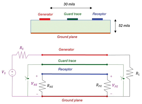
Figure 2 shows the details of PCB topology.

Time Domain Measurement Setup and Results
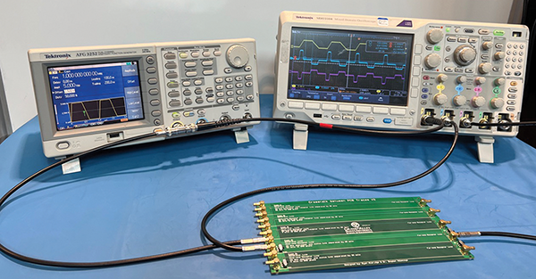
The setup for time domain crosstalk measurements is shown in Figure 3.
Figures 4 and 5 show the generator signal, VS, as well as the resulting near-end voltage, VNE, and far-end voltage, VFE, induced in the receptor circuit. The source signal is an open-circuit voltage 0-5 Vpp, 1-MHz trapezoidal pulse train having 100-ns rise time, 200-ns fall time, and a 50% duty cycle.
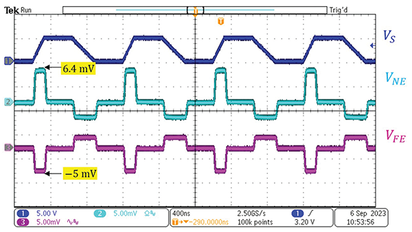
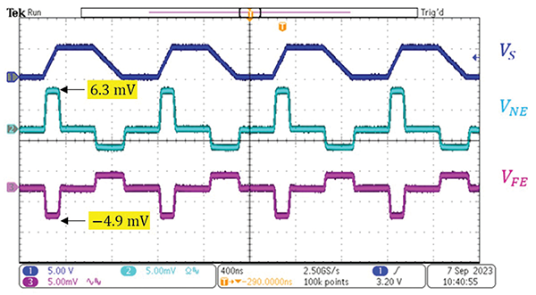
Figure 4 shows the results with no shield, while Figure 5 shows the results with the shield floating (not connected to ground). It is apparent that a floating shield has virtually no effect on the crosstalk-induced voltages.
Figure 6 shows the results when the shield is grounded at the near end while the far end is open.
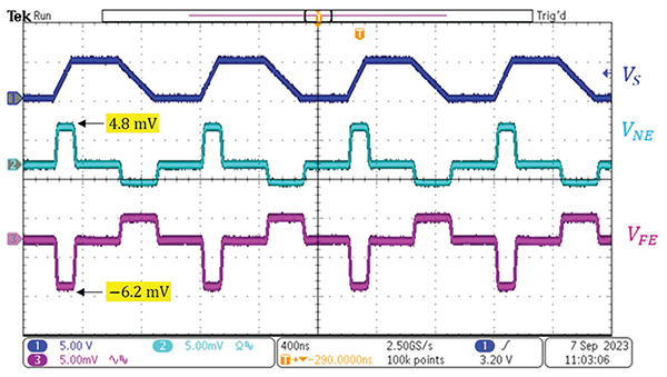
Figure 7 shows the results when the shield is grounded at the far end while the near end is open.
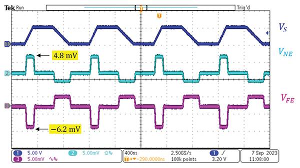
The results show that grounding the shield only at one end decreases the near-end voltage while increasing (in the absolute sense) the far-end voltage. How can this happen? We will answer this question shortly.
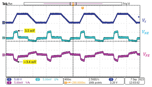
Figure 8 shows the results when the shield is grounded at both ends. Grounding the shield at both ends reduces both the near-end and far-end induced voltages. Table 1 summarizes the results.
| Shield Connection | VNE [mV] | VFE [mV] |
| floating | 6.3 | -4.9 |
| NE grounded, FE open | 4.8 | -6.2 |
| FE grounded, NE open | 4.8 | -6.2 |
| grounded at both ends | 3.5 | -3.4 |
Table 1: Summary of the time domain results
As noted earlier, when the shield was grounded at either end, the near-end voltage decreased while the far-end voltage increased. To explain this phenomenon, we need to look at the formulas governing these voltages [3].
 (1)
(1)
 (2)
(2)
Note that both terms in the expression for the near-end voltage are positive. When the shield is grounded at one end, inductive coupling does not change, while the capacitive coupling is reduced. Thus, the sum of the inductive and capacitive coupling is reduced.
At the far end, the expression for inductive coupling is negative, while the expression for the capacitive coupling is positive. When the shield is grounded at one end, inductive coupling does not change (from the ungrounded case), while the capacitive coupling is reduced. On a microstrip PCB, the inductive coupling usually dominates the capacitive coupling [4]. Effectively, the sum of the inductive and capacitive couplings (crosstalk) at the far end may increase (in the absolute sense) when the shield is grounded only at one end.
Frequency Domain Measurement Setup
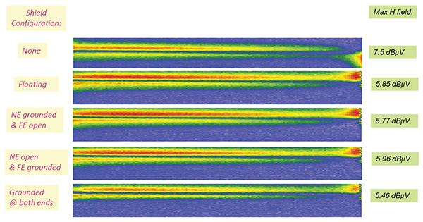
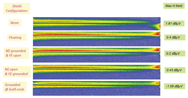
The setup for the near-field H-probe measurements is shown in Figure 9.
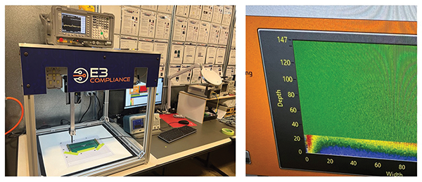
The source signal had the same parameters as in the time domain setup, except for the rise and fall times, which were set to 10 ns. The H-field probe in the near-field scanner took measurements at 9 MHz and 49 MHz.
Figure 10 shows the measurement results at 9 MHz, while Figure 11 shows the results at 49 MHz. Table 2 summarizes these measurements.
| Shield Configuration | Hmax @ 9 MHz [dBµV] | Hmax @ 49 MHz [dBµV] |
| none | 7.5 | 1.81 |
| floating | 5.85 | 0.4 |
| NE grounded, FE open | 5.77 | 0.2 |
| FE grounded, NE open | 5.96 | 0.43 |
| grounded at both ends | 5.46 | -1.06 |
Table 2: Near field measurement summary
The results show that the shield has a small to no effect on the measurement, regardless of its termination.
References
- Bogdan Adamczyk, Mathew Yerian-French, and Ryan Aldridge, “Crosstalk Between PCB Traces – Time and Frequency Domain Measurements, Part 1: Impact of the Circuit Topology,” In Compliance Magazine, June 2024.
- Bogdan Adamczyk and Ryan Aldridge, “Guard Trace Impact on Crosstalk Reduction Between PCB Traces,” In Compliance Magazine, February 2018.
- Bogdan Adamczyk, Principles of Electromagnetic Compatibility: Laboratory Exercises and Lectures, Wiley, 2024.
- Howard Johnson and Martin Graham, High‑Speed Digital Design – A Handbook of Black Magic, Prentice Hall, 1993.
