S-parameters are very useful to evaluate, understand, and optimize the response of your filters. If you are unfamiliar with this typical tool for RF engineers, this column is for you.
In communication systems, filters are easily designed using very well-known methods based in topology (Bessel, Butterworth, Chebyshev, etc.), cut-off frequencies, ripple/attenuation needs and terminal impedances. But, in EMI, we usually do not know those terminal impedances and that is because it is common to design filters in some kind of trial and error process.
S (scattering) parameters are a well-known circuit analysis technique from RF and microwave electronic designers for linear multiport networks. In these applications, designers usually work with power and impedance.
Low frequency designers work with other parameters as Z (impedance), Y (admittance), and H (hybrid). They usually work (are familiar) with voltage and current.
But, from a theoretical point of view all those parameters are equivalent. They can predict the response of any linear (active or passive) network when you connect at the input and output ports any other signal and termination impedances.
In this article I will use S-parameters in the analysis of a filter for all of you who are not familiar with this kind of tool because for high frequencies, as in EMI design, S-parameters are very useful (voltage and currents are difficult to measure).
Consider for example a low pass filter topology as in Figure 1.

Figure 1: A general low pass passive filter to be analyzed.
Some important ideas about this filter are as follows: i) this is a low pass topology; ii) the number of components will be related to how much the required attenuation for the rejection band is; and iii) the filter works by REFLECTION (you are using inductors and capacitors), so the undesired signal will be filtered by mismatching effects with terminal impedances. Note that if you want to filter by DISSIPATION you will use resistors and ferrites.
If you want to apply classical filter design theory, you will need to specify terminal impedances. The filter will be good or bad in the final application depending on those terminal impedances in the frequency range of interest. Without the value of terminal impedances, it is not possible to design a specific response.
It is common to design the filter for 50Ω terminal impedances. In this way you will be able to use 50Ω connectors, cables, instruments, etc. in your laboratory when testing the circuit. Again, if in your final application there is not 50 ohms in the ports, the filter will work differently.
Consider you design the filter for a cut-off frequency of 17MHz, and you need more than 30dB of attenuation for frequencies of more than 25MHz. For the specified conditions you will need five components (three inductors and two capacitors) and the parasitics of the components and layout will be considered in your design.
With the theoretical design (out of the scope of this article) you can proceed to simulate and measure the filter response. How to do it? Here is where S-parameters can help.
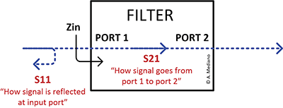
We have four S-parameters for our two ports system: S11, S21, S12, and S22 where S11 and S22 have the meaning of reflection coefficients (in ports 1 and 2 respectively) and S21, S12 have the meaning of transmission coefficients from port 1 to 2 and port 2 to 1 respectively as explained in Figure 2.

Figure 2: Signals trying to pass through the filter.
So, considering S11 and S21 for our two ports filter, a signal going to port 1 will be rejected or accepted by the filter. For undesired signals (frequencies), you will try to offer a big mismatch (s11) at the input port. For desired signals (frequencies) you will try good matching and low loss through the filters.
S-parameters are usually specified in decibels (dB).
If you want to pass a signal through the filter you will look for S11 = -infinite dB so the signal is not reflected in port 1. This is a theoretical (impossible value). We usually look for S11 with values of -12dB to -15dB so more than 90% of the signal is accepted by the filter.
With the accepted signal, and considering the parasitic ESR (quality) of your components, you will be able to obtain a value close to 0dB in S21 for your desired signals meaning the signal goes to port 2 with minimum attenuation.
For signals you want to reject, you look for S11 close to 0dB (this value means the full signal is reflected) so a negative big value (i.e. -30dB to -80dB) is obtained for S21.
Once you have calculated the nominal value for the components (optimized if necessary through simulation including parasitics), you will need to measure the response of your filter.
A typical instrument for this measurement is a VNA (Vector Network Analyzer). For the low frequency range (some Hertz to 40MHz) you can try Bode 100, from Omicron. This is a typical frequency range for conducted emissions as in 9kHz to 30MHz tests.
For higher frequencies, my recommendation is to use some of the ZNL instruments from Rohde and Schwarz.
Commercial VNAs usually have 50 ohms ports and you can measure S-parameters for that reference impedance.
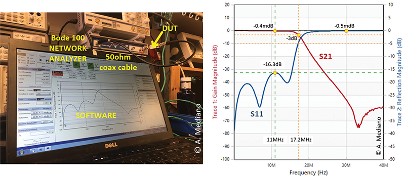
In Figure 3 you can see the setup and response for the filter in our example using the Bode 100 system (50-50 ohms system).

Figure 3: Setup and measurement of the filter
In the measured response, the cut-off frequency (-3dB) is about 17MHz. In the band pass, signals are well matched (S11<-16dB) and they are able to pass to port 2 with minimum losses (S21 close to 0dB).
In the rejected band, signals are strongly attenuated (i.e. S21<-50dB for frequencies higher than 30MHz). In that range of frequencies S11 is close to 0dB meaning signals are fully reflected.
With VNAs you can export the S-parameters to a Touchstone format (the standard for RF industry). The file looks like in Figure 4.

Figure 4: Part of the Touchstone (S-parameters) file of the measured filter.
This information is VERY USEFUL because you will be able to test in your computer the differences when the filter is working with other terminal impedances.
Note the S-parameters file is MEASURED information and it includes effect of quality in components, layout, parasitics, etc. in the filter.
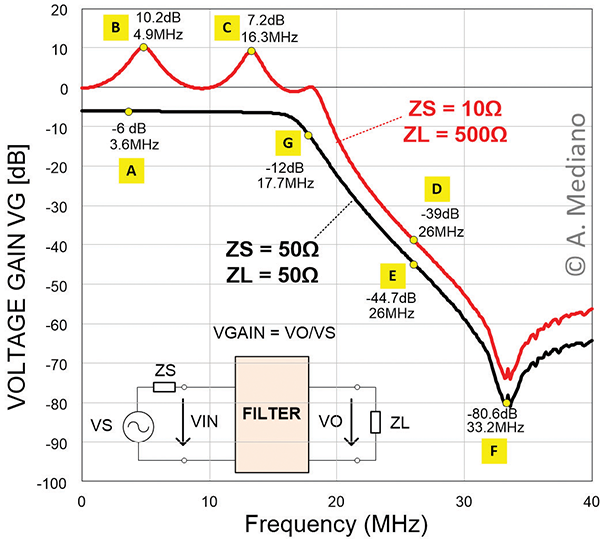
For example, in Figure 5 you can see how is the response of the filter, considering the voltage gain when the signal source is 10Ω and load impedance is 500Ω.

Figure 5: Response of the filter with non 50 ohms terminal impedances.
For the nominal response (black trace) a -6dB in voltage gain (point A) is obtained for the band pass (obviously a perfect match at 50-50 ohms means voltage is half in load for maximum power transfer). For 10-500 ohms (red trace), you can see that attenuation in voltage is close to 8dB lower (points D and E). Additionally you can see the underdamped effect created in points B and C, a typical origin for anomalous increase of EMI at some frequencies as for example 7.4Mhz and 16.3MHz in the graph.
My final advice: learn to use S-parameters in your design process, measure with your network analyzer the response of your designs in a controlled 50-50 ohms setup, export information to a Touchstone file, and evaluate/analyze your situation in the computer analyzing effects like using different terminal impedances.
 Arturo Mediano received his M.Sc. (1990) and his Ph. D. (1997) in Electrical Engineering from University of Zaragoza (Spain), where he has held a teaching professorship in EMI/EMC/RF/SI from 1992. From 1990, he has been involved in R&D projects in EMI/EMC/SI/RF fields for communications, industry and scientific/medical applications with a solid experience in training, consultancy and troubleshooting for companies in Spain, USA, Switzerland, France, UK, Italy, Belgium, Germany, Canada, The Netherlands, Portugal, and Singapore. He is the founder of The HF-Magic Lab®, a specialized laboratory for design, diagnostic, troubleshooting, and training in the EMI/EMC/SI and RF fields at I3A (University of Zaragoza), and from 2011, he is instructor for Besser Associates (CA, USA) offering public and on site courses in EMI/EMC/SI/RF subjects through the USA, especially in Silicon Valley/San Francisco Bay Area. He is Senior Member of the IEEE, active member from 1999 (Chair 2013-2016) of the MTT-17 (HF/VHF/UHF) Technical Committee of the Microwave Theory and Techniques Society and member of the Electromagnetic Compatibility Society. Arturo can be reached at a.mediano@ieee.org. Web: www.cartoontronics.com.

