
Telcordia recently released GR-63-CORE Issue 4 “Physical Protection Requirements for Network Telecommunications Equipment”, with a total of 27 new requirements (Rs) and objectives (Os). It has been six years since the document was updated and, as in previous releases, the specification has numerous technical changes.
The first change you will notice is the reactivation of Section 3. Going back to the Issue 2 version of the specification in 2002, Section 3 was a look forward to generic framework requirements. In the Issue 3 release of 2006, this section was deleted from the document and was left dormant. For the Issue 4 release, the section is activated and renamed as “Equipment Spatial Design Requirements for Frames and Chassis”. Activating this section allows for segregation between the office space planning requirements (Rs) and objectives (Os) and equipment spatial Rs and Os. In Section 4, some of the technical changes that will be reviewed include a new operational high temperature requirement based on the airflow of the equipment under test (EUT), new energy efficiency requirements, and an optional operational random vibration test, to name a few. Some tests remain unchanged and will be skipped in this recap. These include surface temperature, mix flowing gas, hygroscopic dust, and acoustics.
Section 2 – Facility and Space Planning Requirements
In previous issues of the document, space planning requirements and objectives were intertwined with test requirements throughout Section 4. In the latest version, the Section 4 Rs and Os dealing with building layouts, such as Central Office Lighting Requirement R4-98 and Objective O4-99, are moved to Section 2 and relabeled as R2-31 and O2-32. Other requirements and objectives that are moved around in the document can be tracked between the versions by using their absolute number, which is the bracketed number in the Rs or Os. By doing this, Sections 3 and 4 have become much cleaner and easier to follow for both manufacturers and laboratories.
Section 3 – Equipment Spatial Design Requirements for Frames and Chassis
Section 3 now defines the spatial requirements for frames and chassis. The section includes most of the original Rs and Os from Section 2 and thirteen new Rs and Os. The thirteen new Rs and Os include R3-4 and R3-5 say that access to anchoring bolts is needed when shelves are installed in a frame. R3-7 is that a frame must have the ability to join to an adjacent frame at the top. R3-8 states that a dimensional drawing of the equipment must be supplied and enclosed in the test report. R3-29 demands that the mounting holes for a chassis be a closed slot.
Temperature Testing
For the three storage temperature tests (low-temperature exposure and thermal shock, high relative humidity exposure, and high-temperature exposure and thermal shock) there is no change to the testing. The specification does clarify that testing the units in an unpackaged state is an acceptable test method. It also allows for slower ramp rates during the high humidity exposure test. The slower ramp rates allow the test to remain non-condensing for larger systems.
The operating temperature test has undergone significant changes. An ongoing issue with equipment being supplied to end-users is the airflow cooling pattern they use. Equipment with airflow patterns that deviate from the required preferential pattern of R4-34 or O4-35 will now be tested to a higher operational temperature. The high operational temperature test is performed at either 500C or 550C depending on whether the equipment under test (EUT) is frame level equipment or shelf (chassis) level. Now if the equipment has a non-preferential air intake, i.e. not in the front of the EUT, the maximum operating temperature rises to 600C or 650C depending whether it is a rack or a shelf. These new high temperature requirements are from Table 5-1 and 5-2 of the specification (Figure 1). Equipment with the non-preferential air intake can still be tested to the lower temperature levels if it is supplied and tested with an air deflector or air baffle that changes its air intake to the front of the equipment as stated in O4-36. Another change to the operating temperature profile was done to align the test with the requirements of ETSI EN 300 019-2-3 Class 3.2. During the 96 hour humidity dwell, the temperature and humidity are raised from 280C, 90% RH to 300C, 93% RH.
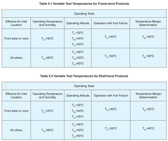
Figure 1: Tables 5.1 and 5.2 from the GR-63-CORE
Altitude, Temperature Margin, Fan Cooled Equipment
Altitude testing remains essentially the same with two exceptions. The temperatures for the test are raised to align with the changes in the operational temperature and humidity test. These temperature changes are also shown in Table 5-1 and 5-2 (Figure 1). The second change is to the alternate altitude test method using temperature compensation. In Issue 3, if the equipment met the configuration criteria to apply the temperature compensation method, it could be used. This entailed adding 10C/1000 feet to the operational temperature. For a shelf level product, the test temperature was 610C, 550C for the operational requirement, and 60C to simulate the 6000 feet from Objective 04-11. Objective 04-12 from Issue 3 is met by default since its required temperature for a shelf product is 580C. In Issue 4, the altitude of the test site can be considered and subtracted from the temperature compensation. If the test site is 3000 feet above sea level, the test will be performed at 580C, 550C from Objective 04-10 and 30C for the altitude compensation ([6,000 feet- 3000 feet(lab ambient)]/1000 feet/10C). Objective
O4-11 will still be met as well.
Temperature margin testing remains unchanged for equipment with front air intakes or equipment with air diverters as previously described. For equipment with air intakes other than the front face, the starting temperature is increased to 600C or 650C as listed in Table 5-1 or Table 5-2.
The fan-cooled equipment criteria changes involve removing the humidity requirement from R4-14. Testing is now performed at either 400C or 500C, depending on airflow, with un-monitored humidity. The other change in the section moves the fan filters requirements from paragraph 4.5.4 in Issue 3 to 4.1.5.2 in Issue 4.
Heat Dissipation, Airflow and Energy Efficiency
Heat dissipation remains as it was in Issue 3. Some guidance on how to perform the calculations is added by stepping through an example in paragraph 5.1.6. This provides consistency between manufacturers on how to report the value. Along with the standard heat dissipation calculation, there is a new requirement R4-31 for energy efficiency. The requirement directs you to use the Alliance for Telecommunication Industry Solutions ATIS-0600015. The document listed is a general requirement document and one of seven documents presently in that ATIS family. Based on the type of equipment being tested, you default to one of those documents (listed at the end of the article). If your equipment does not fit in one of those categories, you default to a telecommunications carrier document such as Verizon’s VZ.TPR.9205 and then to an industry standard document.
The next section in the document with changes is equipment airflow. A large part of the telecommunication service providers (TSP) cost is energy usage for environmental control of their equipment space. One of the major contributors to the high cost is a mixture of equipment with contrasting airflow patterns; hot air exhausting into the cool air aisle. To standardize equipment airflow in the equipment space, the objectives in this section are turned into requirements. As mentioned above, if the EUT deviates from the acceptable airflow pattern, operating temperature testing is performed 100C higher than the previous standard. If an air baffle is used during the qualification to redirect the air to the proper pattern, then the test can be performed at the lower high temperature levels.
Fire Resistance
After the major changes that fire resistance went through for the Issue 3 update, including scaling of the line burner, the changes in Issue 4 are relatively small but still significant. The first change in the section deals with high velocity fans internal to the EUT. It’s not uncommon during full scale fire resistance testing for the line burner to consistently self-extinguish due to the high velocity airflow. Once the protocol of ATIS-0600319.2008 has been completed and the EUT has complied due to the line burner self-extinguishing, one additional burn for that location will need to be performed. That burn will be done with the fans in a non-operating mode in accordance with two new objectives 04-44 for frames or O4-50 for shelves. The second change deals with printed circuit boards (PCBs) having a distance to each other equal to or greater than 25 mm. Under Issue 3, varying distances between the adjacent cards caused no change in the burn profile. The new Issue 4 protocol for adjacent PCBs greater than 25mm away, is to leave the PCB in place and insert the line burner through the faceplate on the component side of the card. The line burner peak flow rate is then calculated in the same way as other burns, using the vertical height of the card and adjusted to 50% of the calculated flow rate.
Mechanical Testing
The Category “A” packaged drop test is updated to change the required (1) edge and (2) corners the packaged product is dropped on. The change was performed to align with shipping industry standards .The number of drops remained at a total of 13.
The unpackaged drop is the key change in this section for equipment weighing less than 25 kg. The traditional free fall flat drops onto a non-yielding surface (concrete) from 3.9 inches or 3 inches, depending on its weight, remains, but the number of flat drops was increased to all possible rest surfaces. The two corner drops and two edge drops were changed to pivot drops. These pivot drops, known in the industry as a bench handling, were adopted from MIL-STD-810G Procedure VI of Method 516. The new test procedure is to place the unpackaged, unpowered equipment onto a wooden bench surface or non-yielding surface on its normal rest face. While using one edge as a pivot point, the opposite edge is lifted 4 inches or 450, whichever is less. The elevated edge is then allowed to free fall onto the bench top. This procedure is then repeated for the pivot edge and the two adjacent edges along the bottom. The drop sequence is then repeated for any other surface the unit could be rested on normally. If your item is able to be rested on a bench top on any of the surfaces, the number of drops would increase from the five required in Issue 3 to 30 in Issue 4. The 30 drops would include six free fall drops, one of each face, and 24 pivot drops, four on each face’s edge.
Seismic testing has a clarification on which bolt the load cell should be placed on during the test if concrete anchors are omitted from the testing. The load cell is placed on the bolt at the innermost position, if the framework allows for a variety of anchor locations. In the test cases that were analyzed, this position was found to have the highest loads relative to the other mounting bolts locations. The second clarification is for testing of multiple shelves in a single frame. In accordance with the specification, units weighing less than 23 kg have to be placed at the top of the rack. In order to allow multiple units to undergo seismic testing in a single frame, direction is given that the smallest unit is to be placed at the top of the rack at the highest location. However. the lowest unit still has to be within the top 20% of the frame.
Office vibration has an additional test option to use a random vibration profile in lieu of the traditional 0.1 g sine sweep. The random vibration curve was adopted from the Class 4M5 requirements of EN ETSI 019-2-4
to align testing with European requirements. The issue with this alignment, done to reduce testing, will be the fixture requirements from each of the documents. GR-63-CORE has the requirement that shelf level products are placed at a specified height in a telecom frame depending on their weight. ETSI EN 300 019-2-4 requires that the test article be placed in a rigid fixture per IEC 60068-2-47, which telecom two-post frames do not comply to. However since European requirements for weather-protected equipment is performed to Class 3.2 of EN ETSI 019-2-3, the Issue 4 test curve is +3 dB higher as shown below (Figure 2). Based on this difference, a response accelerometer can be placed at the mounting location of the EUT in the telecom frame to verify it envelopes the Class 3.2 requirements. If it does not, separate tests will need to be performed for each of the documents.

Figure 2
The final change in the document in the acoustic section is the removal of the acceptance criteria for unattended locations. ![]()
References
ETSI EN 300 019-2-3 v2.2.2 (2003-04) – Environmental Conditions and environmental tests for telecommunications equipment; Part 2-3: Specification of environmental tests; Stationary use at weatherprotected locations.
ETSI EN 300 019-2-4 v2.2.2 (2003-04) – Environmental Conditions and environmental tests for telecommunications equipment; Part 2-4: Specification of environmental tests; Stationary use at non-weatherprotected locations.
ATIS-0600015.2009 – Energy Efficiency for Telecommunication Equipment: Methodology for Measurement and Reporting – General Requirements.
ATIS-0600015.01.2009 – Energy Efficiency for Telecommunication Equipment: Methodology for Measurement and Reporting — Server Requirements.
ATIS-0600015.02.2009 – Energy Efficiency for Telecommunication Equipment: Methodology for Measurement and Reporting – Transport Requirements.
ATIS-0600015.03.2009 – Energy Efficiency for Telecommunications Equipment: Methodology for Measurement and Reporting for Router and Ethernet Switch Products.
ATIS-0600015.04.2010 – Energy Efficiency for Telecommunication Equipment: Methodology for Measurement and Reporting DC Power Plant – Rectifier Requirements.
ATIS-0600015.05.2010 – Energy Efficiency for Telecommunication Equipment: Methodology for Measurement and Reporting Facility Energy Efficiency.
ATIS-0600015.06.2011 – Energy Efficiency for Telecommunication Equipment: Methodology for Measurement and Reporting of Radio Base Station Metrics.
ATIS-0600319.2008 – Equipment Assemblies—Fire Propagation Risk Assessment Criteria.
MIL-STD-810G October 31, 2008 – Department of Defense Test Method Standard Environmental Engineering Considerations and Laboratory Tests.
VZ.TPR.9305 Issue 4, May 2011 – Verizon NEBSTM Compliance: NEBS Compliance Requirements for Telecommunications Equipment.
VZ.TPR.9205 Issue 5, October 2011 – Verizon NEBSTM Compliance: Energy Efficiency Clarification Document.
 |
Clayton Forbes has been working in the testing industry for 30 years, 24 of those years with NTS. Currently he is the Operations manager for NTS’ Northeast Division and was a member of the GR-63-CORE re-write committee. Clayton has served as a technical advisor on various committees in both the commercial and military industries He is presently serving his second term as Vice Chair for the ATIS STEP-NPP committee and also participate on the SC-135 committee who’s responsibilities include RTCA/160 specification. |