
Over the past few years, the standard RTCA/DO-160, Section 22 has undergone multiple revisions. As a member of the Aerospace Test Industry, I regularly receive articles and news informing me of the latest changes being implemented to the standard. However, for others who are new to the requirements, many questions are left unanswered. In my travels, I am often asked the same fundamental questions. This article is intended to introduce the requirements of DO-160, Section 22, and to address some of those fundamental questions.
What is the RTCA?
To better understand the RTCA as it applies to Section 22, let’s take a look at the Foreword for DO-160 Version F.
Who is RTCA?
The Radio Technical Commission for Aeronautics, organized in 1935 and now known as RTCA, Inc. includes roughly 335 government, industry and academic organizations from the United States and around the world. For a clear understanding of the organization we refer to the Foreword: RTCA, Incorporated is a not-for-profit corporation formed to advance the art and science of aviation and aviation electronic systems for the benefit of the public. The organization functions as a Federal Advisory Committee and develops consensus based recommendations on contemporary aviation issues. [1]
Author’s Commentary: This means that the requirements in RTCA DO-160 F are Advisory requirements, not Mandatory requirements.
What are RTCA’s Objectives?
Again, let us refer to the Foreword for DO 160F to answer this question. RTCA’s objectives include but are not limited to:
- coalescing aviation system user and provider technical requirements in a manner that helps government and industry meet their mutual objectives and responsibilities;
Author’s Commentary: They mediate requirements between Aircraft part manufacturers, aircraft manufacturers, and Airlines.
- analyzing and recommending solutions to the system technical issues that aviation faces as it continues to pursue increased safety, system capacity and efficiency;
Author’s Commentary: They come up with requirements that try to keep the planes in the air under adverse environmental conditions.
- developing consensus on the application of pertinent technology to fulfill user and provider requirements, including development of minimum operational performance standards for electronic systems and equipment that support aviation;
Author’s Commentary: They get both airplane manufacturers and component manufacturers to agree on a minimum operational performance standard while the product is being stressed (immunity).
and;
- assisting in developing the appropriate technical material upon which positions for the International Civil Aviation Organization and the International Telecommunications Union and other appropriate international organizations can be based.[1]
Author’s Commentary: Worldwide Organizations adopt these requirements as their positions on issues that arise.
How Important are RTCA’s Standards?
Looking again at the Foreword for DO-160F, we learn that the organization’s recommendations are often used as the basis for government and private sector decisions as well as the foundation for many Federal Aviation Administration technical Standard Orders. Since RTCA is not an official agency of the United States Government, its recommendations may not be regarded as statements of official government policy unless so enunciated by the U.S. government organization or agency having statutory jurisdiction over any matters to which the recommendations relate.[1]
Author’s Commentary: When an aircraft manufacturer (Boeing, Airbus, DeHavilland, Embraer, Fairchild, General Dynamics, Goodyear, Grumman, Gulfstream American, etc.) is deciding on purchasing criteria for its Tier one, two and three vendor parts, it can use any or all of the requirements in the standard as part of its buying criteria. That means almost all of the electronics incorporated into an airplane need to meet some part of this standard.
Who Else Uses These Standards?
We find the answer to this question also in the Foreword of the standard: These standards were coordinated by RTCA SC-135 with the European Organisation for Civil Aviation Equipment (EUROCAE) Working Groups (WGs) 14 and 31. EUROCAE concurs with RTCA on the environmental conditions and test procedures set forth herein. When approved by EUROCAE, this document will be identified jointly as RTCA DO-160E/EUROCAE ED-14E.[1]
Author’s Commentary: The Europeans have similar if not identical requirements, when the standard is adopted as RTCA DO-160E/EUROCAE ED-14E.
What is the SAE?
SAE International is a global technology information and standards-setting resource for the aerospace, automotive, and commercial vehicle industries. In addition to standards development and publication, SAE holds annual and biennial conferences and tradeshows, periodic industry seminars, student Collegiate Design competitions, all focused on all facets of transportation.
SAE Aerospace is a sub group of SAE International. Their focus is on writing Aerospace Standards (AS),which apply to missile, airframe, ground support equipment, propulsion, propeller and accessory equipment; Aerospace Recommended Practices (ARP), which provide recommendations for engineering design and provide background information and research to support those recommendations: and Aerospace information Reports (AIR), which contain generally accepted industry engineering data and information.
AE-2 is the SAE Lightning Committee established by the Aerospace Council of SAE. They draft and publish the recommended requirements for Indirect Lightning Strikes, based largely on industry and SAE research and knowledge. These requirements are very often adopted into RTCA by the RTCA SC-135 subcommittee, who is responsible for the content of DO-160.
The fundamental document that defined the environment and test waveforms used in DO-160, Section 22, and accounted for the lightning data and analysis necessary to support these requirements, is SAE ARP5412, “Aircraft Lightning Environment and Related Test Waveforms,” originally published in 1999, and revised to Revision A in 2005. This document explains where the concepts of Multistroke, Multi Burst and the current test waveforms originated.
Changes in Requirements Over the Past Few Years
Many airplane components have to keep working under environmental stress conditions. One of those conditions is lightning. So many airplane manufacturers specify
Section 22 as one of the requirements for critical systems, like guidance, radar, communications, engine control, heat and air controls, etc.
We sometimes think of avionics as being the navigation and communications equipment, but it also includes engine controls, servo motor controllers for control surfaces like ailerons, rudder and flaps, landing gear controls, radar, even satellite TV, Wi-Fi, and entertainment systems.
Revisions E and F of DO 160 are driven by the use of composite materials used for airframe construction on recent planes like the Boeing 787 Dreamliner and Airbus A380 (Figure 1).

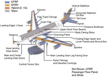
Figure 1: Current and intended uses for composite materials in the construction of airplanes
Carbon Fiber (CF), also known as graphite fiber, or carbon graphite, is a material composed of ultra-thin fibers (0.005-0.010mm diameter) of aligned crystalline Carbon atoms (see Figure 2). The crystalline alignment makes the fiber extremely strong for its size. Thousands of fibers are twisted together to form a yarn, which is often woven into a fabric material. The fiber, combined with a polymer, and heated through various processes, forms a composite material that is extremely strong for its lightweight construction. This lightweight property makes the use of Carbon Fiber Composite (CFC) very attractive to the aerospace industry where weight/thrust ratios are critical for operation, maneuverability, and fuel efficiency.

Figure 2: A single carbon filament (bottom left to top right) laid across a human hair
Prior to CFC materials, the airframe and most other parts of the airplane were made of metal. Thus, if a lightning strike occurred at the nose of the plane, during takeoff for instance, the lightning would travel outside the plane to the tail, exit the surface of the plane, and continue to ground. The solid metal construction of the airframe acted as a Faraday cage, with an extremely low impedance path. This prevented coupling of voltages and currents on the internal wiring of the plane, which usually was routed along the side of the plane, between the inside of the outer skin and the interior bulkhead. This also greatly reduced the susceptibility of the mission critical components located in the plane.
CFC materials, however, don’t conduct lightning currents the way metal airframes do. As a result, the increased impedance of the outer skin as a path for the lightning increases the possibility of higher voltages and currents coupling directly onto internal cables and into the avionics equipment on the aircraft.
RTCA’s Multi Stroke, Multi Burst and SAE’s ARP5412 Revision A
For the newly initiated, DO-160F currently calls out six individual waveforms. Understanding why these waveforms were incorporated into DO-160 comes from referencing the previously mentioned Aerospace Recommended Practice (ARP) 5412 rev. A. Under the scope of the document, the “standardized external current waveforms have in turn been used to derive standardized transient voltage and current waveforms which can be expected to appear on the cable bundles and at equipment interfaces. The test waveforms are considered to be adequate for the demonstration of compliance for the protection of an aircraft and its systems against the lightning environment.” [2]
ARP5412 rev A (hereafter referred to as ARP5412) devotes an entire section to the description of lightning and the variety of forms that lightning can occur. Lightning flashes are the discharging of strong electric fields, or charge centers, within cumulonimbus clouds (Cumulonimbus clouds can form alone, in clusters, or along a cold front in a squall line. They create lightning through the heart of the cloud). There are three types of lightning flashes which may occur:
- Flashes between cloud regions of opposite polarity within the same cloud called intra cloud discharges
- Flashes between cloud regions of opposite polarity in different clouds called inter cloud discharges
- Flashes from clouds to ground or the reverse (in instances of high ground locations like mountains and towers)
When a negative cloud to ground flash occurs, the discharge process starts with the formation of a 1-10m wide ionized column that travels in zigzag steps toward the earth. The leader may form branches on the way down to the ground. When the leader gets close to the ground, it causes buildup of high fields near trees and buildings. These then send up leaders to meet the tip of the downward leader. When they meet, a return stroke is initiated, retracing and discharging the leader channel, resulting in a bright flash and high current pulse. After the initial return stroke, subsequent strokes can occur from higher regions of the cloud through the downward leader stroke. These subsequent strokes are usually of lower amplitude than the initial return stroke.
This is the idealized basis for the Multi Stroke Test parameters of DO-160, Section 22. An illustration from the standard is shown in Figure 3. The initial stroke is the highest amplitude of the Multi Stroke application, with subsequent strokes (up to 14) at a lower but repeated amplitude.
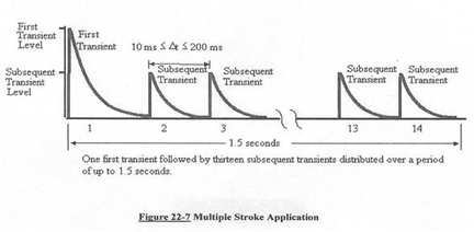
Figure 3: Multi Stroke Application of a Waveform
Inter- and Intra- cloud discharges behave differently than cloud to ground (and vice-versa) discharges. Most of the data recorded for inter- and intra- cloud discharges come from instrumented aircraft employed in the USA and France to record the characteristics of these types of flashes. Although cloud flashes are less severe than flashes to the ground, it was noted that the rise time of the cloud flashes were significantly shorter (less than 0.4 us) and often occurred in grouped pulses during the initial attachment and final detachment phases of the discharges. These short duration, lower amplitude initial and final phases are the basis for the Multi Burst application of Waveform 3. An illustration of the Multiburst Waveform set is shown in Figure 4. One burst is normally composed of 20 pulses.

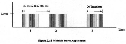
Figure 4: Multi Burst Application of Waveform 3
Waveforms 1, 2, 3, 4, 5A and 5B
We now jump to section 7 of ARP5412, which describes the idealized transient waveforms intended for verification of adequate protection of systems and equipment from indirect lightning effects. This section states that there are multiple mechanisms that can induce lightning transients inside the plane from the external lightning environment, but broadly divides them into 2 categories: Aperture Coupling and Resistive Coupling.
Actual induced transients are complex waveforms that result from both coupling methods, but for test purposes, they have been kept separate. ARP5412 states that magnetic fields penetrating through apertures (electromagnetically transparent openings) will induce:
- a current waveshape in conductors or shields terminated to the structure through low impedances at each end (Figure 5)
- a voltage waveshape in loops existing between cables and the structure (Figure 6)
- damped oscillatory voltage and current waveforms resulting from excited resonances on coupled interior cables. 1MHz and 10 MHz frequencies representing long and short cable lengths, respectively. (Figure 7)

Double exponential 6.4us X 69us (to 50%)
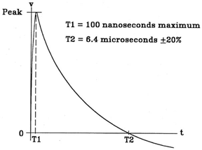
Double exponential 100ns X 6.4us (at zero crossing)

Ringing wave, sine or cosine 1MHz and 10MHz
Resistive Coupling will produce:
- voltages in conductors within shields due to shield current and shield transfer impedance (Figure 8) and
- voltages produced by loops existing between cables and the airframe structure (resulting from variances in voltage from the endpoint locations of the cable at different locations on the airframe) and voltages resulting from diffused fields through the structural material (Figure 9). Figure 9 shows 2 different waveforms to cover the wide variance of frame resistance represented by metal and carbon fiber composite airframes.
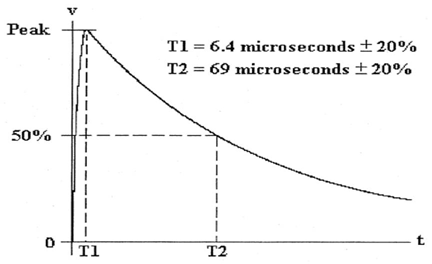
Double Exponential 6.4us x 69us (to 50%)

Double Exponential 40us X 120us (to 50%)
Waveform 5B – Voltage/Current
Double Exponential 50us X 500us (to 50%)
Waveform Power Levels
There are five Test Power Levels, where Level 1 is the lowest and Level 5 is the highest.
- Level 1
- Equipment and wiring are installed in a well protected environment
- Level 2
- Equipment and wiring are in a partially protected environment
- Level 3
- Equipment and wiring are in a moderate electromagnetic environment
- Level 4 and 5
- Equipment and wiring are in severe electromagnetic environments
Power levels specified in DO-160 Section 22 are often based upon how critical the component is for flight operation and/or where the unit is located within the aircraft. Greater resistance or spacing from apertures will result in lower power levels. Power levels can also be dictated by the component purchaser or plane manufacturer, based upon other factors. An example is a plane manufacturer may wish to increase the immunity level of entertainment systems on long range aircraft, with the idea that they are more likely to experience multiple lightning strikes and more likely to fail during a 14 hour flight.
Testing Methods
There are three primary methods of testing aircraft components
Pin Injection – This method is used to directly inject the waveform into connector pins of both cables and printed wiring boards.
Cable Bundle Induction– This method uses a coupling transformer to inductively couple the waveform onto the cable bundle.
Ground Injection – This method is often used as an alternate method to inject the waveform onto the ground wire of the unit under test, referenced to the Ground plane that is located on the surface of the test table.
Methods of testing are often dictated by the purchaser, using categorizations defined in DO-160, and involving specific waveform sets for different coupling means. Figure 10 shows the Table for Pin Injection for both aperture coupling and resistive and aperture coupling, and specifies which waveforms are to be applied.
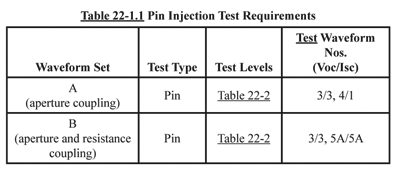
Figure 10
Figure 11 shows the table for Cable Bundle Induction Testing, and indicates the categories for various Aperture and Resistive Couplings. Figure 12 shows an example of a Cable Bundle Injection Transformer.

Figure 11
As defined in Figures 10 and 11:
a. A, C, E, G and J are for aperture coupling
b. B, D, F, H, and K are for resistance coupling
c. A and B specify Pin Injection
d. C through F specify cable bundle single stroke
e. G through K specify cable bundle single, multi-stroke and multi-burst
f. Z means other tests were conducted
These letters (A-K, Z) are used as part of a classification code often provided by the buyer (Airplane Manufacturer) who determines what coupling may occur and what induced conditions may be expected on their airplane, based upon construction materials, unit location and expected coupling zones.
MIL STD 461
The content presented above represents an explanation of the fundamentals of DO-160Section 22 Testing for Indirect Lightning effects. Understanding the origins and justifications of the requirements often help in determining the course of action needed to test a product. Current expectations are that the requirements listed in DO-160 Section 22 will be adopted by MIL STD 461 in 2011.![]()
References
- RTCA/DO-160F Environmental Conditions and Test Procedures for Airborne Equipment
- SAE ARP5412-RevA-2005 Aircraft Lightning Environment and Related