 How do you construct a building without metallic components of any kind? When you are engineers charged with overseeing the design and construction of an Open Area Test Site (OATS) for your company, you find out very quickly how to build a structurally sound facility while still keeping the area free of reflective materials.
The company we work for designs and manufactures Uninterruptible Power Supply (UPS) systems and associated components to support the power availability requirements of data centers and other critical electronic equipment. UPS systems, electrical bypass cabinets, large battery systems, electrical distribution systems and monitoring systems contain microprocessors with high speed switches, and most also contain high current power switches. Both switch types radiate electromagnetic fields and conduct high frequency noise that may potentially exceed the limits for radiated and conducted emissions as defined in the FCC Code of Federal Regulations, Title 47, Part 15.
Due to our tight product development and product release schedules and cost, it became a matter of both pragmatism and economics to build our own test facility. Here’s what the experience was like, and what we learned.
The Presenting Problem
For years, in order to verify the compliance of our products with FCC standards governing electromagnetic interference (EMI), we sent our products to third-party labs. Although these labs are reputable and efficient for many test requirements, we struggled with using these facilities for some of our larger power systems products or products that were on a time-sensitive schedule. The reasons were as follows:
- Power requirements: Our largest unit exceeds 1 Million Volt Amps (MVA). We do not necessarily test at the maximum current, but the startup inrush needs to be taken into consideration. Most outside labs do not have the capacity available to test our units without a rented generator.
- Turntable size: Our units can be large and heavy, with the 1 MVA uninterruptible power supply weighing 20,000 pounds. The typical outside lab turntable cannot accommodate a product this large, or the weight of the forklift required to move the product onto the table.
- Sound measurements: Another portion of our testing includes measuring the audible noise that a product creates. For acoustical noise testing, the challenges of physical size and supplied power that exist with EMI and electromagnetic compatibility (EMC) testing still apply, only now with the additional requirements of the appropriate ambient environment and room construction.
Considering the Options for a Test Facility
First we had to determine which type of facility of the two kinds available was best to perform the radiated and conducted emissions testing in our particular circumstances.
- Semi-Anechoic Chamber (SAC), which allows measurement of equipment emissions by eliminating all external noises via ferrite absorber tiles placed around the room; or
- Open Area Test Site (OATS), which allows measurement of equipment emissions by removing all reflective and absorptive surfaces within a greater-than-ten-meter area.
The SAC, though extremely efficient, had cost estimates for a ten-meter chamber reaching beyond several million dollars. The OATS facility, with a cost under one million dollars (including instrumentation) was much more financially feasible.
By definition, an OATS facility is not actually a building. The ideal OATS is a flat piece of land, free of obstructions, away from any and all external signals, with a perfectly reflective surface. But because our test site would be in an industrial complex next to a small airport, a structure would have to be placed around the reflective ground plane of the OATS, making it less open than the ideal but still approximating ideal conditions. We understood that what we were proposing was a Modified-Open Area Test Site (M-OATS); but during the preliminary discussions with the engineers and contractors involved, the term OATS caught on. This abbreviation was used throughout the project to minimize confusion.
It is not common to construct a building using non-metallic material. Our challenge became striking a balance between keeping the area free of reflective materials for EMC testing and making the framework structurally sound.
Some of the same issues that gave us a challenge at the outside labs came into play in our design and build. Ambient signals are abundant near an airport within a city near a larger metropolitan area. Broadcast TV, AM and FM radio, wireless towers, family radio, air traffic control, emergency dispatchers and now, broadband high definition TV (HDTV), are consuming larger portions of the RF spectrum and can readily be detected by antenna at our location.
Due to these ambient emissions, a careful site survey was conducted prior to site selection, wherein we measured the direction and amplitude of the ambient signal spectrum. After reviewing the data, we positioned the building such that, during testing, the receive antenna would be facing away from the highest ambient source(s), attenuating those signals as much as possible.
We also knew wires and conduits were going to be a problem in testing. We had to keep metal of any type to a minimum anywhere close to the receive antenna, an area that comically came to be called the “cone of silence.” This term was used to help explain to individuals such as the architect and the building contractor that the three-dimensional space around the test area had to be kept clear of metallic objects of any size from the ground plane to the height of the trusses. As we explain below, this was easier said than done.

Typical ambient noise sweep graph
Top 10 List: Not Your Usual Construction Issues
Our customers expect conditioned, uninterrupted power with ratings up to 8 MVA for multi-module systems, and up to 1.1 MVA for single-module systems. We chose 1.5 MVA as the test rating point, with the expectation of expanding capacity in the near future, when the power feed will be increased. The building size and specifications were based on these requirements. As we proceeded, we had to deal with a laundry list of issues and considerations, among which included:
- The planned building height entailed submitting plans to the local building authority for approval.
- Since the facility is located next to an airport, the FAA needed to know and approve the building height. This was a lengthy process.
- To limit metallic content, outlets had to be located either outside the “cone of silence” or in the floor below the ground plane.
- Framing was nonmetallic, and minimal fasteners were used to reduce RF reflections. The wall and ceiling consisted of Structural Insulated Panels (SIP). Drywall was placed over the SIP for fire code compliance and will accommodate more reverberant sound measurements that will be used in the next development phase of the building.
- Due to the prohibitive cost of a restroom, we decided not to install one in favor of using the main building’s facility.
- Our turntable was designed to lift 36,000 pounds and accommodate a unit up to 18 feet wide. Rotation could not be electrical.
- Again, to limit metallic content above the ground plane, ambient lighting had to be installed in the floor as opposed to above ground.
- Due to cost and potentially increased reflections, heating and cooling of the OATS became a concern. Because of the structurally insulated panels, the building has a high insulating rating and, therefore, heating of the building would come from the lighting in the floor (with additional heat provided by the natural heat losses of the product itself being tested.) Cooling of the control room was achieved by installation of a small air conditioning unit, below grade and away from the “cone of silence.”
- Reflective fire extinguishers had to be positioned outside of the “cone of silence,” but still within easy access, if needed.
- The electromagnetic field (EMF) associated with flights taking off and landing at the local airport had to be identified in order to keep these distinct from our own measurements.
Best Practices Note: To make code approval a smoother process, talk to the local inspector and discuss the goals of your project. Getting input on the front end will ensure that issues are addressed early in the design and build, and they can give you expert insight. They will also appreciate not being blindsided during inspection. Likewise, assume that the architect and turntable manufacturers will not be familiar with EMC testing, and educate them at the outset to ensure that their deliverables are in line with your needs and expectations.
Making Sure We Stood Up to Scrutiny
In order to accept EMI measurements inside of the OATS, the site had to be validated in a process called Normalized Site Attenuation (NSA) testing. As described in ANSI C63.4-2003, this process is intended to ensure that the reflective/absorptive losses at the site are comparable to the standard’s theoretical values. Essentially, it was our task to ensure that the OATS we had spent so much time developing, from design to construction, met the standard requirements in order to actually be utilized.
Using Log-Periodic and Biconical antennas, we performed a volumetric test on the ten-meter area between the turntable and the future location of the receive antenna mast. In the NSA test, a signal was injected into a transmit antenna and then received, over the air and across the OATS ground plane, by another antenna. The received signals were measured on an EMI receiver and the difference between the transmitted and received decibel values documented. We then compared this number to a theoretical value in the standard. To validate the site, in accordance with the ANSI standard, the documented value had to be within +/-4dB of the theoretical value.
This NSA test was performed for four transmit antenna positions around the perimeter of the turntable (and one in the center). In the instances of the leftmost and rightmost positions, the inside edge of the antenna remained outside the planned volume of our largest product to be tested. This would ensure that reliable data would be gathered when testing, no matter the product size, so long as it was placed within the tested volume. In all, when considering the repositioning of the transmit antenna, the adjusted height of the transmit antenna (per ANSI C63.4-2003), and the adjustment of the receive antenna between heights of one meter to four meters, some six hundred measurements were made over the course of an entire work week.
The results were generally similar to the theoretical values. But there were some points in the building that required modification in order to meet NSA expectations. Exit signs on the side entrance of the building had to be replaced with the phosphorescent variety; this required removing the wiring and conduit previously in place. Copper brushes were sought to better connect the turntable to the ground plane, electrically speaking. With each alteration, the decibel measurements better aligned with the theoretical values.
Some changes have taken place since NSA testing, including the addition of an air cooling/condenser system in the control room, switchgear conduit, indicator lights, and an Emergency Power Off (EPO) push button above the ground plane. With continual improvements and additions to the facility, validation of the site will need to be performed on an annual basis to guarantee continued confidence in the building.

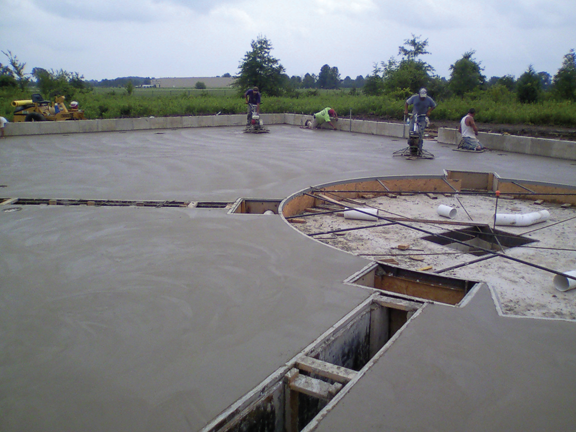
Floor construction showing turntable and foundation

Ground plane assembly
Best Practices Note: In order to operate with maximum efficiency, we experimented with LED light fixtures to illuminate some of the rooms in the OATS building. The LED lights required a voltage transformer to convert 120 VAC to the lower LED voltage. The transformer radiated noise exceeding tolerances to allow for compliance testing, so LED technology is not recommended for an OATS test facility.
With validation of the OATS facility completed, along with the removal of known radiated EMI sources, numerous UPS and ancillary products have made their way through the doors of the building. Over the last two years, radiated and conducted EMI testing has been performed on many products, ranging from 1 MVA UPSs to 120 VAC printed circuit boards. In each case, testing proceeded with relatively few problems related to the test setup itself, while offering reliable, supportable data.
In order to validate the tests in the OATS facility, we retested equipment that was previously tested in third-party labs. The radiated EMI results were comparable with those taken in a separate semi-anechoic chamber for one product, and data retrieved from conducted EMI testing for another matched the results taken on a previously constructed ground plane (from which data had been shown to be similar to that of a third-party laboratory). After all of the hard work involved, it was gratifying to see the OATS facility operational, in use, and producing verifiable, satisfactory data.

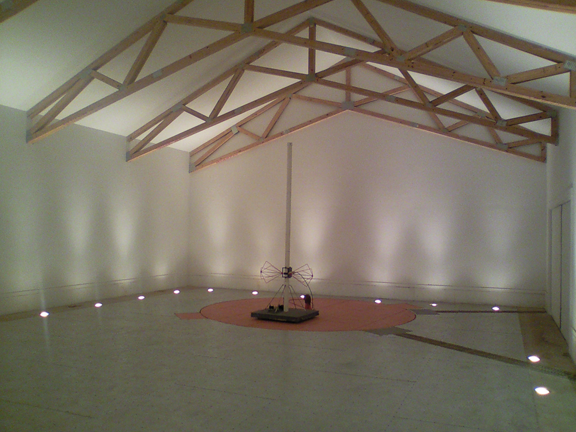
Completed interior test cell
What is next in the OATS story?
Since the validation process, we have modified the OATS by either adding or removing elements that we considered after the preliminary work.
Even the inclusion of safety items that must be kept on premises requires evaluation for their radio frequency interaction. Along with annual evaluations, scrutinizing normal everyday items and their locations has become a matter of routine, while still following the local fire and building codes.
Testing must be monitored and controlled by qualified personnel, which requires further education for the EMI/EMC compliance technicians and engineers. In-house training and outside courses are provided for the EMI/EMC technicians and engineers. The new facility requires a different set of procedures than typical test facilities; technicians need to study and understand everything from setup to standards to ensure proper operation and maintenance of the site. This will continue to be an ongoing requirement, but will allow the OATS to grow and be a cornerstone in testing.
Budget
A development team included members from our design group, an architect, a construction contractor, and our own facility engineers which worked with a nine-month timeline. Testing instrumentation was included in the budget. Some existing equipment, such as spectrum analyzers and antennas, were already being utilized onsite and could easily be moved into the OATS facility but we also wanted equipment with increased scope, sensitivity, automation, networking features, and enhanced user interface. With the budget provided, we estimated a return on investment of 1.8 years vs. outsourcing the testing of our equipment for EMC. This does not include the benefit of faster time to market.
What would we have done differently, if our budget had been larger?
- Installed an even larger turntable.
- Allotted for more power to the unit under test.
- Cleared an even greater area surrounding the OATS –our NSA measurements were decent enough but unexplained reflections still occurred on the far side of the turntable nearest a sizable wooded area.
- Installed an HVAC system – though the temperature is typically within reason, there can be extremes in January and August when the facility is no longer “user friendly.”
- Provided increased storage capacity for equipment, tools and components – most of the initially designed storage space came to be consumed by power feed switchgear. An additional area for storage would have increased efficiency and saved time in gathering tools/components.
- Placed ancillary equipment below grade (ground plane) – most of our equipment resides beyond the measurement ellipse and has not proven to be an issue; however, placing it below grade would have helped reduce any unrecognized reflections and may have helped in creating more precise NSA measurements.
- Utilized more fiberglass than wood –wood begins to develop reflective properties at higher frequencies and thus we are open to measurementconcerns as we go beyond 1 GHz. This could require more frequent NSA surveys to verify compliance.
There are many challenges presented when developing and designing an OATS, specifically one with such extraordinary power and spacing requirements. In addition to EMC-related needs, there are architectural requirements, city and county codes and regulations, and personal budgets which must be taken into account. Our task was slightly unique considering our product line and also our location inside of a very active RF transmission area but we overcame these obstacles and constructed a reliable test site. Since the building was completed, we have run numerous tests on several different products with results comparable to those of an established, qualified third-party laboratory. In all, the success of our OATS depended upon advance planning, proactive approaches to known issues, communication with outside parties, inclusive team meetings, and a commitment to designing a facility without abandoning quality or efficiency. ![]()
 |
James K. Martin P.E. has worked for thirty-two years as a UPS designer at Emerson Network Power / Liebert in Delaware, Ohio. He holds a BSEET in Electronic Engineering through Franklin University and a BSEE in Power Systems through The Ohio State University. Additionally, he has worked as a consulting engineer during his lengthy career. He can be reached at jim.martin@emerson.com. |
 |
Scott Pansing began his career as an Industrial Electrician and received his Associate Degree through CPI in Columbus, Ohio. He has spent twenty years in the electrical, electronic and automation industry, having worked within the EMC/EMI field for the past eight years at Emerson Network Power in Delaware, Ohio. He can be reached at scott.pansing@emerson.com. |
 |
Andrew Bellamy has seven years’ experience in the power electronics industry, four years specifically related to electromagnetic compatibility while employed with Emerson Network Power in Delaware, Ohio. He has an Associate Degree in Electronic Engineering through North Central State College, is a graduate of Global EMC University, and is certified as an iNARTE EMC Technician. He can be reached at andrew.bellamy@emerson.com. |
